
How Thin Can Walls Be Before Short Shots Occur?
工艺参数17 min read
On this page
A product design reduced wall thickness from 0mm to 0.5mm,, cutting weight by 30% and cost by 20%. Trial molding resulted in short shots; three rounds of process adjustments failed.
The problem isn't the process—it's the flow ratio. This article explains how to calculate minimum wall thickness.
What is Flow Ratio?
Flow ratio is the flow length divided by wall thickness. Flow length refers to the actual path distance from the gate to the farthest point in the cavity, not the straight-line distance.
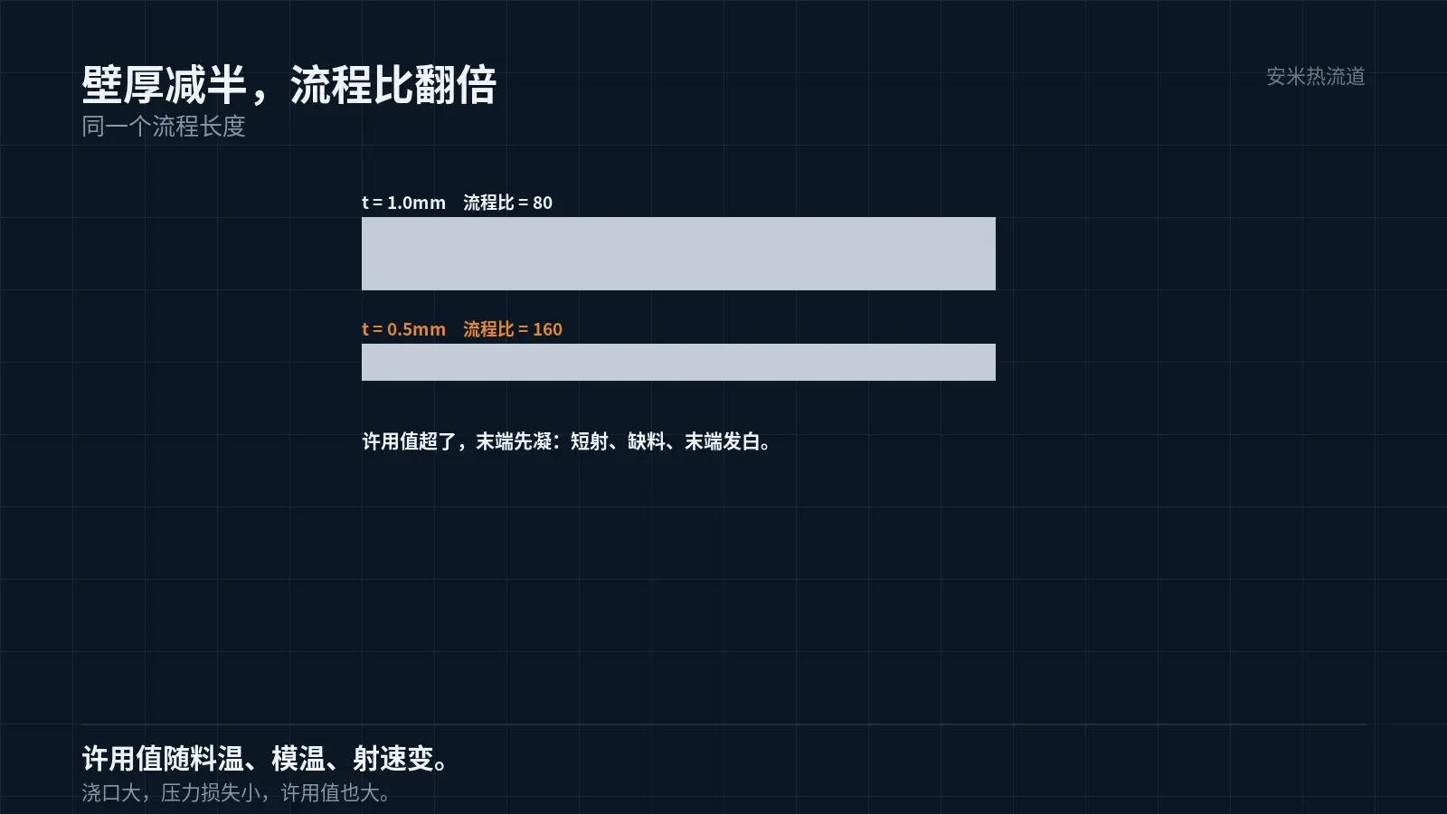
Halving the wall thickness doubles the flow ratio. Doubling it significantly increases filling resistance and required injection pressure.
If the flow ratio exceeds the material's allowable limit, the melt solidifies before reaching the end. Symptoms include short shots, incomplete filling, and whitening at the tip.
The allowable limit is not fixed; it varies by material, melt temperature, mold temperature, and injection speed. For the same material, a higher melt temperature permits a higher limit.
Gate size is another variable. Larger gates reduce pressure loss, enabling a higher usable flow ratio.
Therefore, flow ratio, gate, melt temperature, and mold temperature are interdependent. Evaluating any one in isolation yields inaccurate results.
Therefore, you must evaluate whether the wall thickness is sufficient in conjunction with the process. With the same wall thickness, optimized processes achieve complete filling, while poor processes lead to short shots.
Approximate ranges for various materials
Unreinforced PA and POM exhibit high allowable flow ratios and excellent thin-wall capability. Even at a flow ratio of approximately 100, there is margin for a wall thickness of 0.5 mm.
PA9T and PA46 with 30% glass fiber exhibit moderate allowable values. At a wall thickness of 0.4 mm, exercise caution when the flow ratio approaches approximately 75.
LCP offers the best thin-wall capability. Thanks to its low viscosity and rapid solidification, it can achieve wall thicknesses as low as 0.2 mm, though it requires high injection speeds and elevated mold temperatures.
PPS with 40% glass fiber has lower allowable values. High glass fiber content increases viscosity, so sufficient margin must be maintained for the flow ratio in thin-wall parts.
These figures are order-of-magnitude estimates, not standards. Actual values should be calculated using mold flow analysis and verified through trial molding.
Mold flow analysis calculates filling pressure and melt front temperature. If the melt front temperature drops below the freezing point, short shots occur. This method is more accurate than empirical estimates.
However, mold flow results depend on material data. Using the wrong grade can cause deviations. Verify the material grade first.
After mold flow analysis, review the front temperature map—not just fillability. Even if filled, low front temperatures can compromise part strength.
Low front temperatures occur where weld lines are weak and internal stress is high, especially on thin walls.
Front temperature also determines weld line strength. If the melt fronts meet at a low temperature, interfacial diffusion is insufficient, leading to weak strength.
Three Process Conditions for Thin Walls
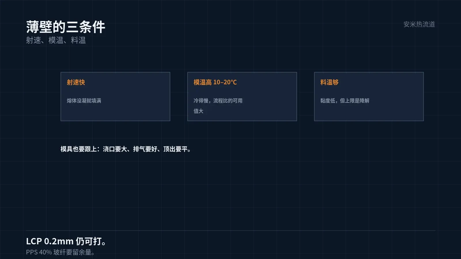
First, injection speed must be high. Thin wall cross-sections are small; the melt cools immediately upon entry and solidifies if the injection is too slow. The injection speed must be fast enough to fill the cavity before solidification occurs.
Second, mold temperature must be high. A higher mold temperature slows melt cooling and increases the effective flow length. For thin-wall parts, the mold temperature is typically 10–20°C higher than for thick-wall parts.
Third, melt temperature must be sufficient. Higher temperatures reduce viscosity and improve fillability. However, the upper limit is degradation; it cannot be increased indefinitely.
Among the three factors, injection speed and mold temperature have the greatest impact. Melt temperature has a narrow operating window; excessive increases can cause degradation.
Therefore, molds for thin-wall parts must withstand high temperatures and rapid filling. Mold temperature control is a prerequisite for thin-wall molding.
Thin-wall mold requirements
First, ensure the gate is large. Thin-walled parts have high flow ratios; small gates cause excessive pressure loss. Gate dimensions must be determined by the flow ratio, not standard conventions.
Second, venting must be effective. Thin-wall filling is fast, leaving insufficient time for air evacuation and causing burn marks at the fill end. Vent grooves must be deep enough and numerous enough.
Third, cooling must be uniform. Thin walls cool quickly but are prone to uneven cooling, leading to noticeable part warpage.
Fourth, ejection must be even. Thin-walled parts lack rigidity; concentrated ejector pins can cause stress whitening and deformation. Ensure the ejection contact area is large.
These four points are mandatory for thin-wall parts. Omitting any one will lead to unstable mass production.
Parts with non-uniform wall thickness
Many parts have non-uniform wall thicknesses due to ribs, bosses, and transitions between thick and thin sections. For such parts, calculate the flow ratio based on the thinnest section.
The thinnest sections freeze first, leaving thicker areas unfilled. This creates a conflict where thin regions solidify prematurely while thick regions experience short shots.
The solution is to modify the structure by using gradual transitions between thick and thin sections instead of abrupt changes. Gradual transitions ensure stable melt flow, while abrupt changes lead to stagnation.
The typical gradient ratio is 1:3, meaning a 1mm thickness change should occur over a 3mm length. Exceeding this ratio increases the risk of sink marks at the transition.
This must be finalized during the design phase, as it cannot be altered after mold trials. Therefore, wall thickness reviews should be conducted early.
Acceptance and Judgment
For short shots in thin-wall parts, first calculate the flow length ratio and verify that process parameters are optimized. If both checks fail, the issue is design-related.
Design changes include increasing wall thickness, moving the gate, adding gates, or switching materials. These four options are listed in order of increasing cost.
Increasing wall thickness impacts weight and assembly; customer approval is required first. Changing materials requires re-certification, which is the most expensive option.
Therefore, thin-wall part feasibility must be evaluated during the design phase. Assessing it after mold completion means costs have already been incurred.
Please provide the part drawing, minimum wall thickness, flow length, and material grade. We will verify based on the flow length ratio and issue a quotation upon confirmation.
MATCHED BY MATERIAL AND DEFECT
This article covers stringing, drooling, clogging, and high-heat resins; refer to SD for gate freeze and break-off.
Register for a selection review and quote
Submit part, mold, and material details. Our engineers will evaluate the gate solution per part and provide a quote.
Upload a 2D layout drawing using the form.
Online selection and quote
Scan to register