
Why Do Long Parts Always Warp? What Does Glass Fiber Orientation Do?
工艺参数17 min read
On this page
A 100×20 mm long bar bows 0.5 mm in the center after molding. Adjusting holding pressure, mold temperature, and cooling does not eliminate the bow.
The issue is not process parameters but orientation. This article explains how orientation causes warpage.
How Orientation Works
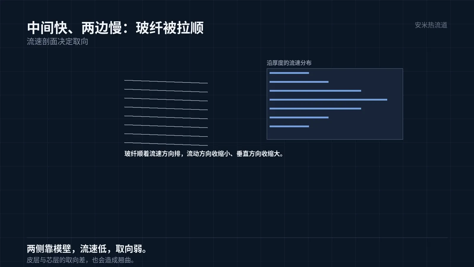
As the melt flows through the cavity, velocity is highest at the center and lowest near the walls. Glass fibers align with the flow direction under shear stress.
Shrinkage is low in the flow direction and high in the transverse direction. This difference causes warpage.
For long bars, flow occurs along the length. Low shrinkage in the longitudinal direction combined with high shrinkage across the width and thickness causes bowing along the bar's length.
The bow direction is determined by the side with stronger orientation. With an end gate, orientation is strongest near the gate and weakest at the far end, which defines the bow direction.
Warpage in long bars stems from combined directional and positional differences. Adjusting only one factor cannot resolve the issue.
Orientation varies through the thickness. Stronger orientation in the skin layer and weaker orientation in the core cause the part to warp toward the highly oriented side during cooling.
The skin-core difference is small in thin walls but significant in thick walls. Consequently, warpage in long thick-walled bars is harder to control than in thin-walled ones.
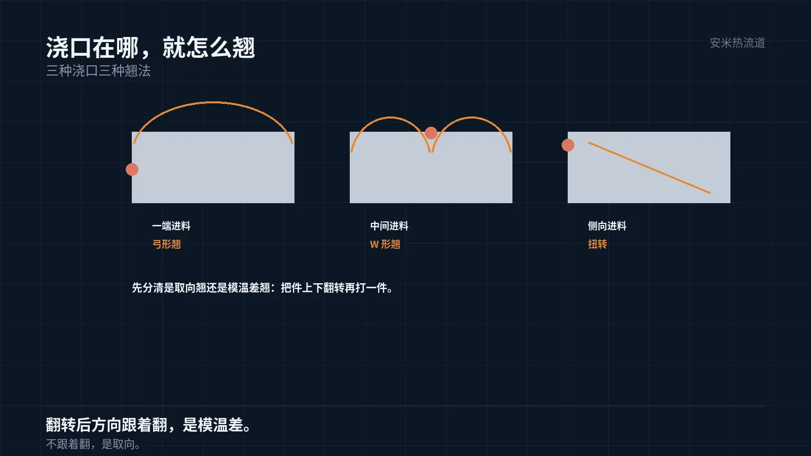
Gate position determines bow direction
With the gate at one end of the long side, melt flows along the length, causing predominant orientation in the longitudinal direction. This leads to "bow-shaped" warpage.
With the gate centered on the long side, melt flow splits toward both ends with symmetrical orientation, leading to easy "W-shaped" warpage.
With the gate positioned on one side of the width, melt flows laterally with dominant transverse orientation, leading to easy "twisting".
Three gate types produce three warpage modes. Therefore, the first step in diagnosing warpage is identifying the gate location.
If the gate cannot be changed, modify the runner system by adding flow dividers or restrictors to redirect melt flow. This requires mold modifications and incurs high costs.
If mold changes are not feasible, rely on process adjustments: optimize mold temperature, injection speed, and holding pressure to minimize directional variations.
Mold temperature differences increase warpage.
Varying mold temperatures between the cavity and core cause uneven cooling on the part's top and bottom surfaces, resulting in differential shrinkage.
The top surface cools and shrinks first, while the bottom surface cools and shrinks later, resulting in upward warping. This warping combines with orientation-induced warping, potentially acting in either opposing or identical directions.
When correcting warpage, first determine if the cause is molecular orientation or mold temperature variation. The corrective actions differ based on the root cause.
Mold temperature variations arise from both cooling channel design and the thermal properties of cavity and core steels. Beryllium copper cores exhibit higher thermal conductivity, leading to elevated temperatures compared to steel cores.
This effect is negligible for thin walls but significant for thick walls. Therefore, core material selection for thick-walled parts must be coordinated with cavity material selection.
Another factor is cooling time. Thick-walled parts cool slowly; if ejected before sufficient in-mold cooling, post-ejection shrinkage continues, worsening warpage.
Extending cooling time reduces warpage but increases cycle time. This trade-off requires capacity calculations, not just quality considerations.
Ejection must be uniform. Insufficient ejector pins or concentrated ejection force creates stress during demolding, increasing warpage.
Diagnostic Method: Flip the part vertically and capture another image. If the warpage direction reverses, it is caused by mold temperature differences; if unchanged, it is due to orientation.
Run this simple, effective test first. Adjusting parameters without identifying the root cause often leads to further instability.
A third cause is uneven cooling. If water flow in one channel is stronger than in the other, the two sides of the part cool at different rates, leading to warpage. While the flip method eliminates mold temperature differences, it cannot eliminate positional variations in the water channels.
Therefore, a complete root cause analysis requires three test groups: normal, flipped, and switched water channels. Comparing these groups identifies the cause.
Process Control Limits
Raising the mold temperature slows melt cooling, giving glass fibers more time to relax. This reduces orientation and warpage.
Reducing injection speed lowers shear and orientation, which helps minimize warpage. However, slower speeds can lead to short shots, particularly in thin-walled, long parts.
Increasing holding pressure improves material compensation, reducing differential shrinkage and warpage. However, higher holding pressure increases internal stress, which can cause warpage after ejection.
Each parameter has limits. The mold temperature upper limit is set by ejection and cycle time; the injection speed lower limit depends on filling capability; and the holding pressure upper limit is constrained by flash and internal stress.
Process adjustments typically reduce warpage by 30–50%. If further reduction is needed, modify the mold or change the material.
Adjustment sequence: adjust mold temperature first, then injection speed, and finally holding pressure. Mold temperature has the greatest impact; holding pressure has the least.
Allow the mold temperature to stabilize after adjustment, typically requiring over 30 minutes. Rushing trials yields inaccurate data.
Material modification: reduce glass fiber content or switch to materials with lower anisotropy. This requires re-certification and incurs high costs.
An often-overlooked approach is to modify the part structure. Adding ribs, increasing wall thickness, or changing cross-sections can significantly improve warp resistance—often more effectively than process adjustments.
Verification: Three-way comparison
Part 1: Standard molding, measure warpage. Part 2: Flip orientation, measure warpage. Part 3: Change gate scheme (if applicable), measure warpage.
Comparing warpage values across the three parts helps identify root causes and their magnitudes. This dataset is more valuable than repeated parameter adjustments.
Submit part drawings, dimensions (L/W/T), gate location, and measured warpage values. We will verify orientation and gate design before providing a quote.
MATCHED BY MATERIAL AND DEFECT
This article covers surface gating or small precision parts; check TP for gate position and whether a dot mark is acceptable.
Register for a selection review and quote
Submit part, mold, and material details. Our engineers will evaluate the gate solution per part and provide a quote.
Upload a 2D layout drawing using the form.
Online selection and quote
Scan to register