
How to choose between pin-point and side gates?
工艺参数16 min read
On this page
For the same part, two mold shops proposed different gate designs: one pin-point gate and one side gate. Both claim no quality impact, but prices differ by 15%.
The differences lie not in quality, but in gate removal, venting, and mold design. This article compares them item by item.
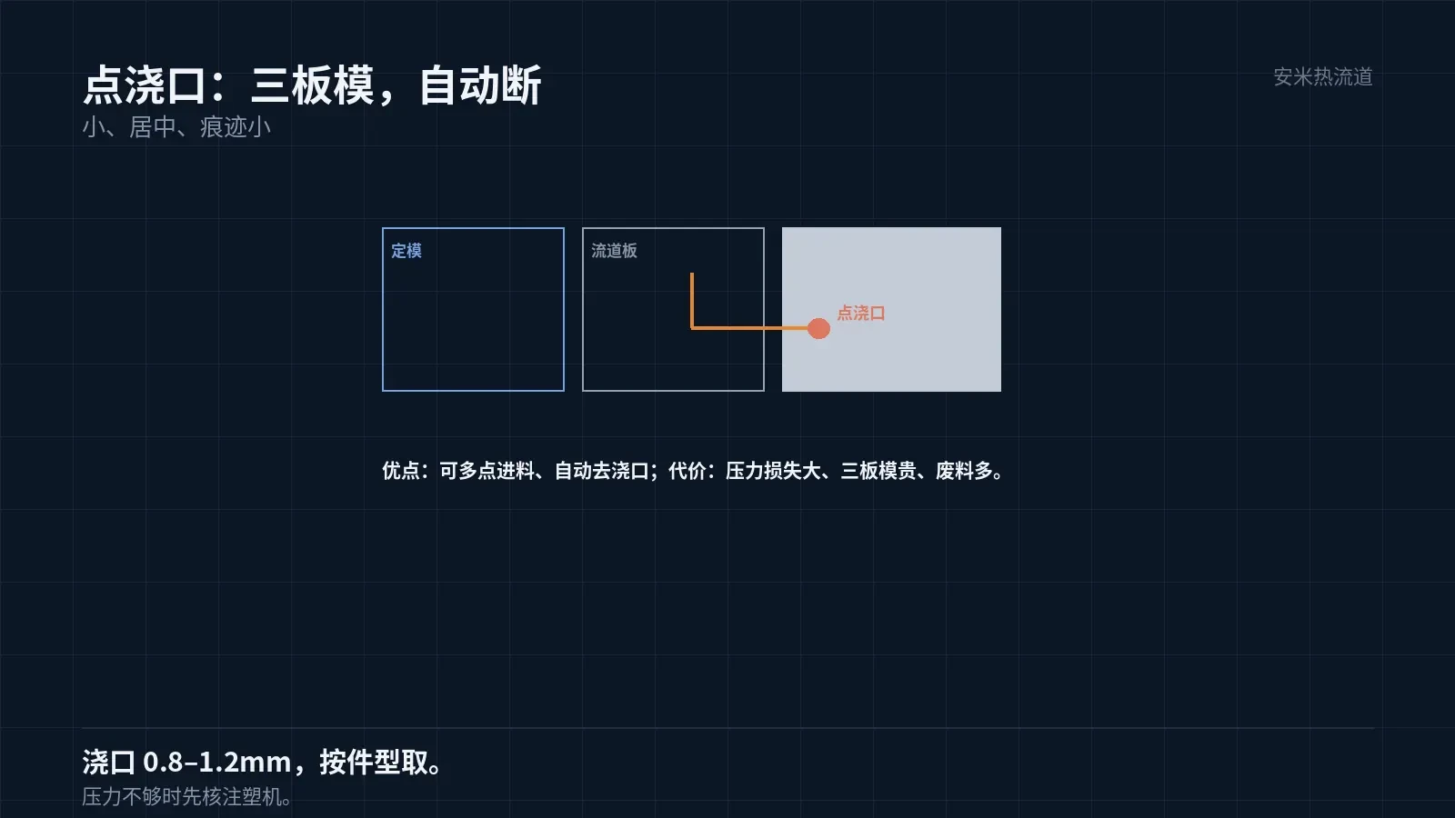
Pinpoint Gate: Small, Centered, Automatic Break-off
A pinpoint gate injects material at a specific location on the cavity. The gate diameter is small, typically 0.8–1.2mm.. After injection, the gate breaks off automatically, leaving a small nub on the part.
Advantages: Flexible gate location (center or multi-point); easy gate removal (often automatic drop-off); three-plate mold design enables automatic gate separation.
Disadvantages: Small gate induces high shear, requiring caution with shear-sensitive materials; complex three-plate mold design increases cost; higher runner waste.
Another drawback of pin-point gates is substantial pressure loss. The combination of small gates and long runners requires high injection molding machine pressure.
When pressure is insufficient, operators often raise the melt temperature. Higher temperatures increase degradation risks and make gate stringing more likely.
Verify the injection molding machine's pressure capability before using a pin-point gate design. If pressure is insufficient, the solution will not work.
Pin-point gates are ideal for projects with high cosmetic standards, multi-point gating needs, high volumes, and acceptance of three-plate mold costs.
Pin-point gate diameter must be determined by material and part geometry. A gate that is too small causes high shear stress and filling difficulties; one that is too large results in visible marks and difficult removal.
Common pin-point gate diameters for small parts are 0.8–1.2mm.. Use smaller values for thin-wall parts and larger values for thick-wall parts.
Side gate: Large, edge location. Manual removal required.
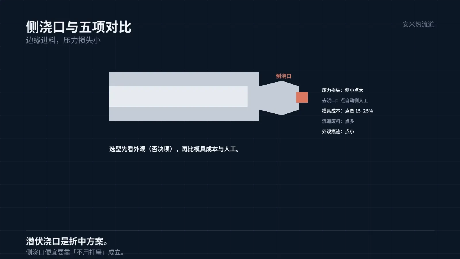
Side gates feed material at the part edge with a relatively large cross-section, typically rectangular or trapezoidal.
Benefits include low pressure loss and easy filling, a simple mold structure compatible with two-plate molds, and suitability for large, thick-walled parts.
Disadvantages include restricted gate locations limited to parting line edges, the need for manual or post-processing gate removal, and visible gate marks.
Side gate marks affect cosmetic parts. Gate locations should be hidden on non-visible surfaces or require post-grinding.
Grinding adds labor, dust, and surface consistency costs. For high-volume production, grinding expenses can exceed the mold cost difference.
The claim that "side gates are cheaper" is only valid if no polishing is needed.
Another benefit: side gates reduce runner scrap, lowering material costs. This is especially significant for high-cost materials.
Scrap reuse depends on the customer. If not allowed, scrap incurs a cost.
Note that the gate-to-part junction must include a fillet radius. Sharp corners concentrate stress and may chip during gate removal.
The fillet radius at the junction must be specified in the drawing, not left to the fitter's discretion. Inconsistent practices among mold makers lead to inconsistent parts.
Therefore, side gates are ideal for large parts, thick walls, low cosmetic requirements, and cost-sensitive projects.
Side gate width and depth must be determined by part geometry. Wider gates improve filling but complicate removal; deeper gates reduce pressure loss but leave deeper marks.
Side gate location also affects weld lines. Placing it at one end creates a weld line on the opposite side; placing it in the middle splits the weld line into two locations.
Item-by-item comparison
Pressure loss: Pinpoint gates incur higher pressure loss than side gates. For thin-walled, long parts, pinpoint gates may require higher injection pressure.
Second, gate removal: pinpoint gates are automatic; side gates require manual labor. For high-volume parts, labor costs are high.
Third, mold cost: pin-point gates require three-plate molds, increasing costs by 15–25%; side gates use two-plate molds, resulting in lower costs.
Fourth, runner waste: pin-point gates generate more scrap, increasing material costs; side gates produce less waste.
5. Appearance: Pin-point gates leave a small nub; side gates leave visible marks. Pin-point gates are typically used for cosmetic parts.
The first three factors determine cost; the last two determine quality. Select by meeting quality requirements first, then compare costs.
There's also a hidden cost: setup time. Pin-point gates cause higher pressure loss and require longer setup, while side gates are easier to adjust and reduce setup time.
This factor is often overlooked in quotes but impacts delivery schedules. It becomes critical when project timelines are tight.
Third option: submarine gate
The tab gate is an edge-gate variant concealed within the part interior or at hidden edges, and it shears off automatically during mold opening.
It combines the automatic break-off of pinpoint gates with the low pressure loss of edge gates, but requires complex mold structures and high machining precision.
Tab gate placement is limited to areas near the parting line and cannot be used if the part geometry does not permit.
In practice, selection typically involves choosing one of three gate types: pin-point, edge, or tab, each designed for specific use cases.
Another type is the direct gate, used for single-cavity large parts. It offers minimal pressure loss but leaves the largest gate mark and makes gate removal most difficult.
Three Gate Selection Criteria
First, evaluate cosmetic requirements. Cosmetic parts should use pinpoint or tab gates; non-cosmetic parts may use edge gates.
Second, consider wall thickness and flow length. Thin-walled parts with long flow paths require low pressure loss, making edge gates or hot runners more suitable.
Third, evaluate production volume. High volumes favor automated gate removal to save labor; for low volumes, manual removal is cost-effective.
Among these, the first criterion is a veto factor: if cosmetic standards are not met, lower costs do not matter.
Please provide the part drawing, appearance requirements, batch size, and existing injection molding machine tonnage. We will verify based on the gate type before providing a quote.
MATCHED BY MATERIAL AND DEFECT
This article covers stringing, drooling, clogging, and high-heat resins; refer to SD for gate freeze and break-off.
Register for a selection review and quote
Submit part, mold, and material details. Our engineers will evaluate the gate solution per part and provide a quote.
Upload a 2D layout drawing using the form.
Online selection and quote
Scan to register