
Why Cycle Time Increases More Than Expected When Wall Thickness Grows?
工艺参数18 min read
On this page
Increasing wall thickness from 1.0mm to 1.5mm increases weight by 50% and cycle time from 12s to 22s. The customer expected a 50% cycle increase, but the actual increase was 80%.
Cooling time scales with the square of wall thickness. This article explains how to calculate it.
Cooling Time Square Relationship
Cooling time is roughly proportional to the square of wall thickness. Doubling the wall thickness quadruples the cooling time.
This is because heat must travel from the center to the surface. Doubling the path length more than doubles the heat transfer time due to changing temperature gradients.
Therefore, even small increases in wall thickness lead to significant cycle time increases. This drives the economics of thin-wall design.
Conversely, reducing wall thickness is the most effective way to shorten cycle time—more so than adjusting cooling channels or mold temperature.
Consider this during cost accounting: quoting based solely on material price without factoring in cycle time will lead to losses.
Calculation method: Convert cycle time to machine hours and multiply by the hourly rate. An 80% increase in cycle time raises per-part processing costs by 80%.
Many quotes cover only material and tooling costs, excluding machine time. For thick-walled parts, this component accounts for a significant portion of the total cost.
Machine time is calculated based on the number of cavities and cycle time. For a single-cavity mold, the machine time per part is eight times that of an eight-cavity mold.
Competitors often leverage this during price comparisons. Lower quotes frequently exclude machine time costs.
Accurate machine time calculations build confidence in your quotes. When customers ask, "Why is your price higher than others?", you can clearly itemize the costs.
Quotes without clear justification rely solely on price cuts, ultimately compromising quality.
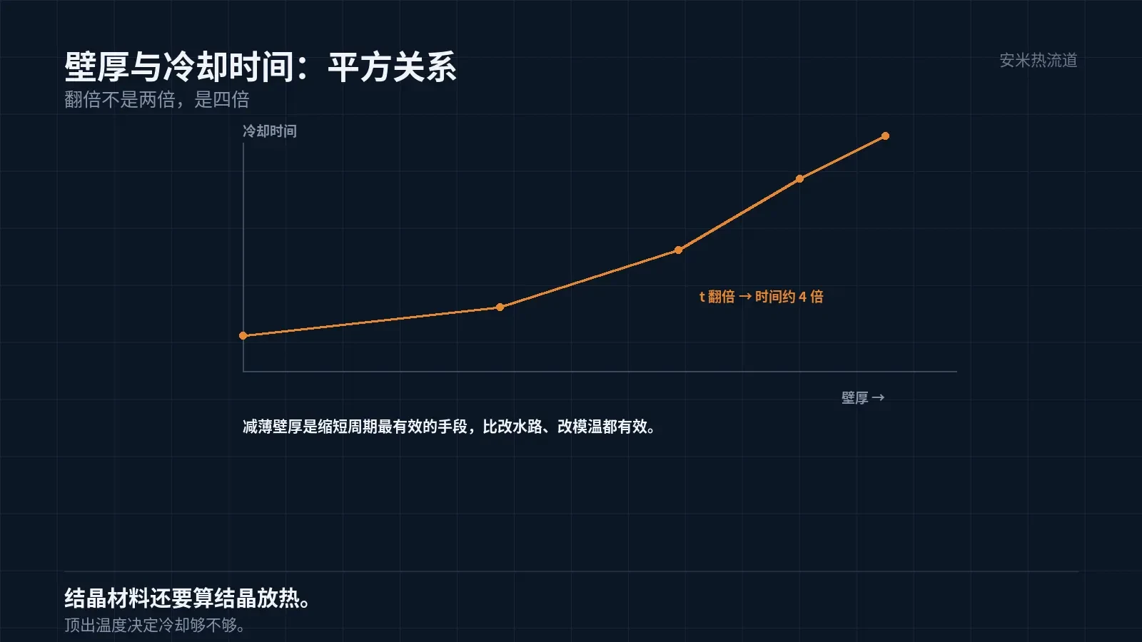
Cooling Time Estimation
A common engineering rule of thumb states that cooling time is proportional to the square of wall thickness, with the coefficient determined by the material's thermal diffusivity.
For semi-crystalline materials (PA, POM, PPS, PEEK), the coefficient is lower than for amorphous materials (PC, PEI) because crystallization heat release extends cooling time.
Use the formula for initial estimation, then refine via trial molding. The formula gives the order of magnitude; trial molding delivers the actual value.
Adjustments are based on actual part temperature. If the ejection temperature is too high, cooling time is insufficient; if too low, cooling time is excessive.
Ejection temperature is typically assessed by touch or with an infrared thermometer. For high-precision applications, use in-mold sensors.
Empirical ejection temperatures: for amorphous materials, 20–30°C below Tg; for crystalline materials, approximately 60°C below the melting point. These are approximate values; verify by material grade.
If the temperature exceeds this value, the part deforms after ejection; if below, cooling time is wasted.
Measurement method: Immediately measure the part surface temperature and cavity temperature after ejection. Close agreement between the two indicates adequate cooling.
Measure at the thickest point. By the time the thickest area reaches the target temperature, other areas will have cooled sufficiently.
In-mold sensors directly measure cavity temperature with greater accuracy than infrared thermometers. This setup is ideal for high-precision applications.
Sensor positions must align with the part's critical dimensions. Incorrect measurement points render data meaningless.
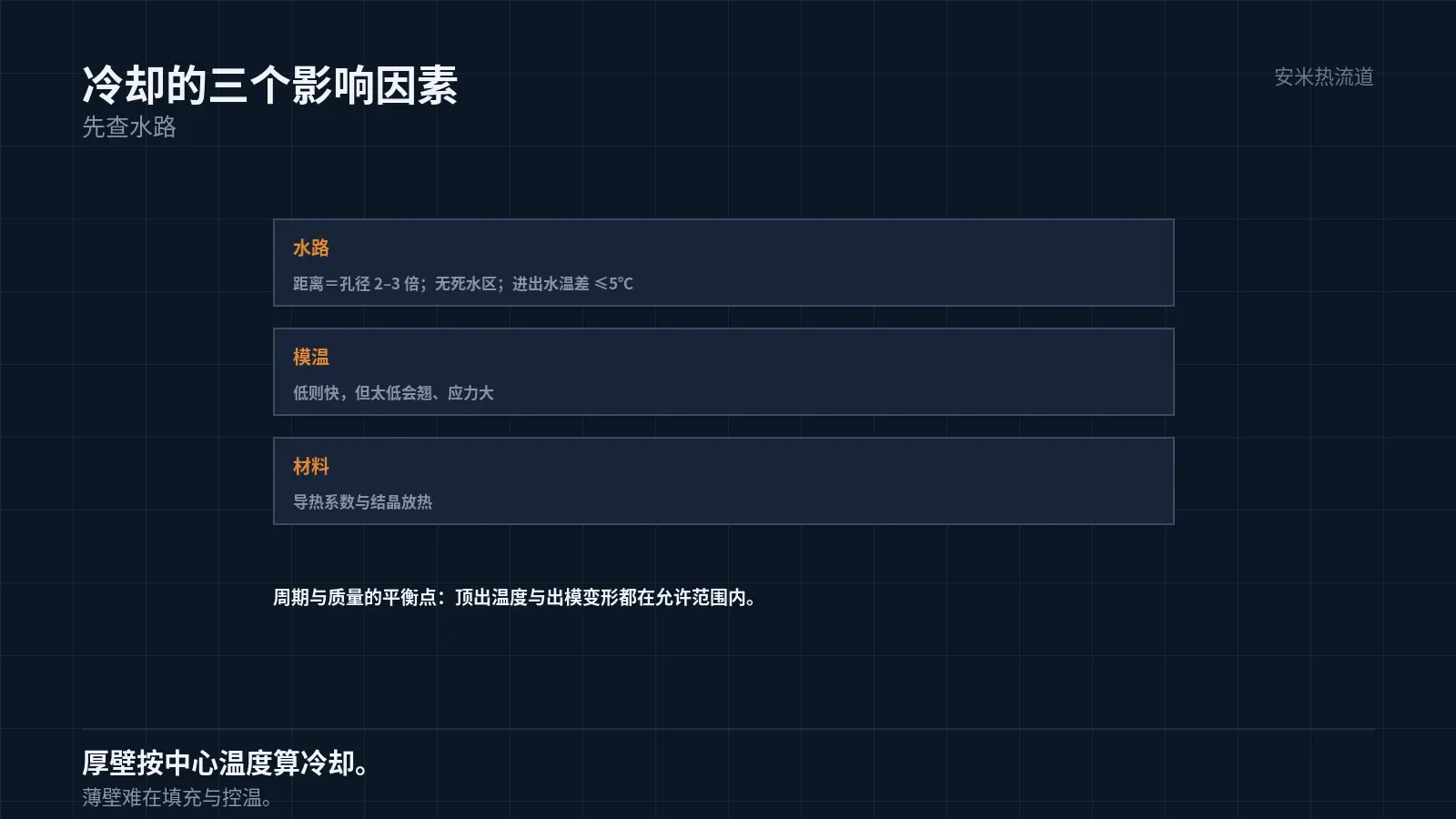
Three Factors Affecting Cooling Time
First, set the mold temperature. A lower temperature accelerates cooling but can lead to warpage and high residual stress if too low. Optimize mold temperature to balance part quality and cycle time.
Second, cooling channels. Proximity to the cavity, sufficient flow rate, and turbulent flow enable fast cooling. Channel spacing is typically 2–3 times the diameter.
Third, material. High thermal conductivity materials cool faster. Glass fiber reinforcement enhances thermal conductivity, slightly accelerating cooling.
Among these three factors, cooling channels have the greatest impact, followed by mold temperature, then material. To reduce cycle time, inspect cooling channels first.
Cooling channel inspection is specific: verify flow sufficiency, dead zones, and inlet-outlet temperature difference. All three are measurable.
Special Issues with Thick-Walled Components
The center of thick sections cools last. Ejecting before full solidification can cause shrinkage, sinks, or warping.
Therefore, cooling time for thick-walled parts must be based on center temperature, not average temperature. This point is often overlooked.
Thick-walled parts also experience uneven internal and external cooling, which creates residual stress. This can cause gradual deformation or cracking after demolding.
Solutions: Extend cooling time, increase mold temperature, or perform post-processing (annealing). Annealing relieves stress but adds an extra process step.
Therefore, thick-wall part processes have long cycle times and high risks. Both factors must be included in quotes.
The Other Side of Thin-Wall Parts
Thin-wall parts cool quickly with short cycles, but filling is challenging. High injection speed and pressure are required, demanding greater machine capabilities.
Temperature control for thin-wall parts is highly sensitive. A 5°C variation in mold temperature causes significant dimensional deviation.
Therefore, molds for thin-wall parts require zoned water circuits and precise temperature control. Water circuit costs are higher than those for thick-wall parts.
This factor is frequently underestimated in quotes. Mold costs for thin-wall parts include not only machining fees but also the temperature control system.
Thin-wall and thick-wall parts pose different challenges; one solution won't work for both.
Balancing Cycle Time and Quality
Short cooling times enable faster cycles but increase warpage, sink marks, and stress. Long cooling times ensure stable quality but reduce throughput.
Adjust cooling time based on part application. Cosmetic and precision parts require adequate cooling; structural and non-cosmetic parts can use shorter cycles.
Judgment criteria: ejection temperature and post-ejection deformation. If both are within allowable limits, the cooling time is sufficient.
Compromise approach: If in-mold cooling is insufficient, use a post-demolding fixture for shaping. This reduces cycle time but requires additional equipment and labor.
This method is commonly used for thin-walled large parts. Fixture costs are lower than mold water line modifications.
Send us the part drawing, wall thickness, material grade, current cycle time, and ejection temperature. We'll review cooling and cycle time, then provide a quote upon confirmation.
MATCHED BY MATERIAL AND DEFECT
This article covers stringing, drooling, clogging, and high-heat resins; refer to SD for gate freeze and break-off.
Register for a selection review and quote
Submit part, mold, and material details. Our engineers will evaluate the gate solution per part and provide a quote.
Upload a 2D layout drawing using the form.
Online selection and quote
Scan to register