
Persistent Sink Marks in Thick Areas Despite Increased Packing Pressure
工艺参数18 min read
On this page
For parts with bosses, a depression typically appears on the boss back. Increasing holding pressure from 60 to 90 slightly reduced sink marks but caused flash.
Sink marks are not caused by insufficient holding pressure, but because thick sections cannot be fully packed. This article explains the mechanism behind uneven wall thickness.
Sink Marks: Causes and Characteristics
Melt volume shrinks during cooling. Thicker sections have larger volumes and greater shrinkage. Shrinkage requires packing via holding pressure; if no additional material can be added, depressions will form.
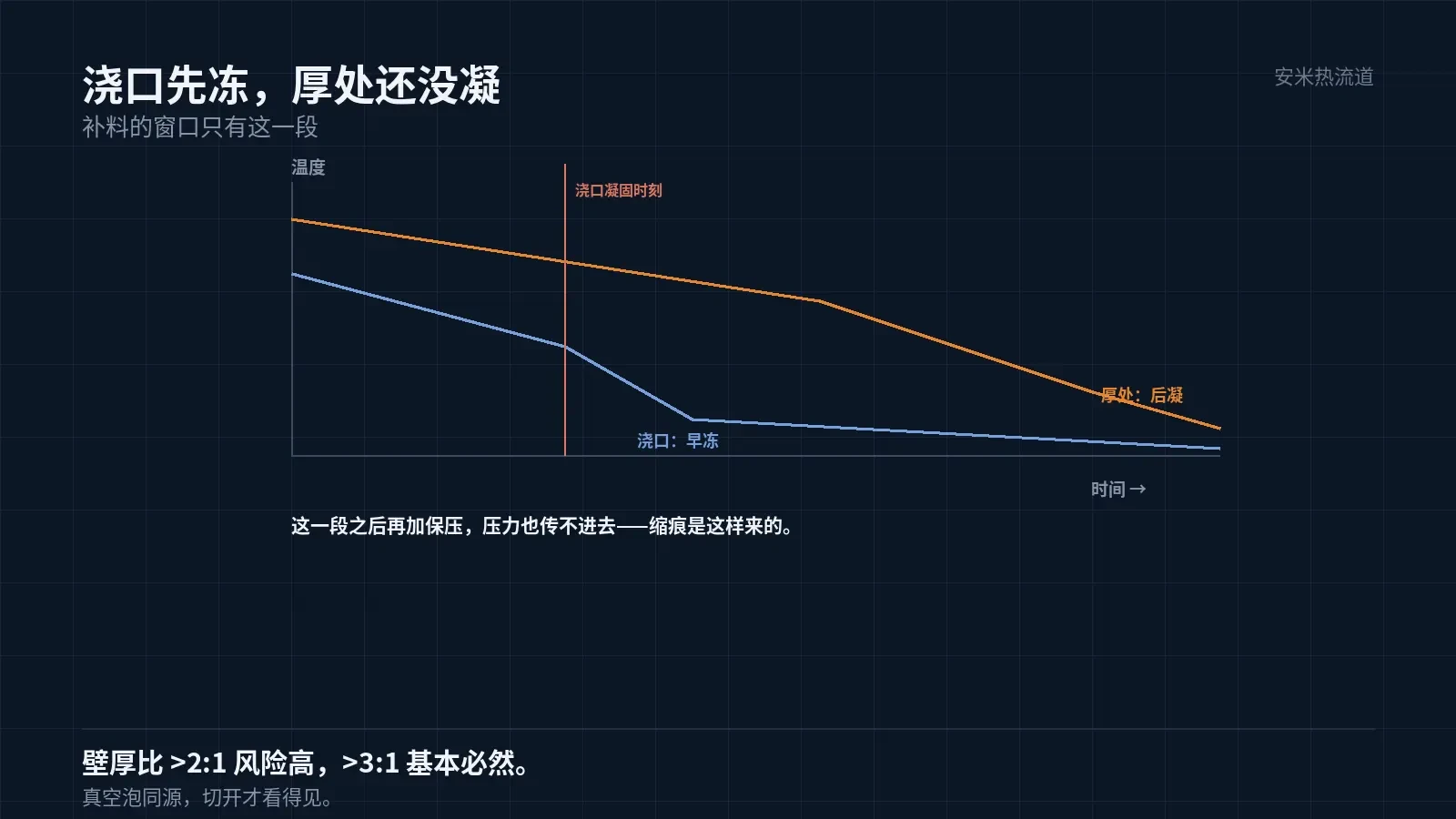
Packing requires two conditions: the gate must remain unfrozen and the flow path open. Once the gate freezes, holding pressure cannot transmit into the cavity, even at higher levels.
Thick sections are often far from the gate and cool slowly, leading to a "gate freezes before the thick section solidifies." This time lag creates the window for sink marks.
Therefore, the root cause of sink marks is this time lag—not insufficient pressure. Increasing pressure can only slightly reduce sink marks, not eliminate them.
Another factor is the wall thickness ratio. If a thick section exceeds twice the thickness of an adjacent thin section, sink marks will almost certainly occur.
A close relative of sink marks is vacuum voids. These are invisible on the surface but appear as internal cavities when cut open. They form because the center shrinks after the surface has already solidified, creating a volumetric void.
Vacuum voids and sink marks share the same root cause: insufficient packing. The key difference is that sink marks are visible, while vacuum voids are hidden and pose a greater risk.
Vacuum void inspection requires sectioning or X-ray. For batch sampling, inspecting one part is sufficient.
Section at the thickest area. Vacuum voids appear in thick sections; thin sections show no evidence when cut.
Preventing vacuum voids requires more than just packing: minimize wall thickness variation. Smaller differences reduce the likelihood of voids.
This approach is more effective than process adjustment. Structural modification addresses the root cause; process tuning only mitigates symptoms.
Wall Thickness Ratio Limits
Empirically, if the wall thickness ratio between adjacent areas exceeds 2:1, the risk of sink marks increases. If it exceeds 3:1, sink marks are virtually inevitable.
Design specs often state "wall thickness ratio ≤ 2." This isn't a conservative guess—it's based on sink mark analysis.
Bosses, ribs, and studs on parts are local thickened areas. The back sides of these locations are high-risk zones for sink marks.
Rib thickness is typically 0.5–0.7 times the wall thickness. Excessive rib thickness causes sink marks on the back; insufficient thickness leads to short shots in the rib.
This is determined during structural design. Once the mold is complete, only structural modifications or accepting sink marks remain as options.
Rib roots require fillets. Sharp rib roots cause melt stagnation and stress concentration, resulting in sink marks and fractures.
Fillet radius is typically half the rib thickness. Proper filleting reduces sink mark depth and increases strength.
Rib orientation matters: ribs parallel to melt flow aid filling, while perpendicular ribs increase resistance and risk short shots.
Multiple rib intersections are the thickest areas and show the most severe sink marks. These must be thinned.
Thinning is achieved by staggering intersections so that two ribs do not meet at the same point, reducing local thickness.
Slight staggering reduces structural strength. This trade-off must be confirmed with the structural engineer.
Process Capabilities
First, extend the holding pressure time. A longer hold delays gate freeze-off, enabling more material compensation. However, gate freezing depends on gate size and cooling conditions.
Second, increase the mold temperature. Higher mold temperatures slow melt cooling and extend packing time, but they also increase cycle time and may worsen warpage.
Third, local heating. Install heater rods near thick sections to delay solidification. This approach is used in precision molds but comes at a high cost.
Fourth, adjust the gate position. Placing the gate near thick sections shortens the packing path and reduces sink marks. This is often overlooked but highly effective.
Among the four methods, gate position has the greatest impact, followed by mold temperature, then holding pressure. Reversing this order leads to "increasing pressure until flash occurs."

Structural modifications
First, hollow out thick sections. Hollow the bosses with wall thickness matching the main body to eliminate sink marks.
Second, use gradual transitions in thick sections. Replacing abrupt steps with tapered slopes distributes shrinkage and reduces sink mark depth.
Third, relocate thick sections to non-visible surfaces. Sink marks will still occur but remain hidden. This is a compromise, not a solution.
Fourth, split thick sections into two parts. Assemble the two components with uniform wall thickness each. This changes assembly and requires customer confirmation.
Among the four methods, coring is the most thorough, while gradual transition is the most common. Moving to non-cosmetic surfaces serves as a fallback; splitting parts is the last resort.
Thin-section issues are also significant.
Uneven wall thickness causes opposite issues in thin versus thick sections: thin areas solidify first, resulting in short shots, material shortages, and high internal stress.
High internal stress in thin sections leads to warping and cracking after demolding, particularly at thin-to-thick transitions where stress concentrates.
Therefore, for parts with uneven wall thickness, evaluate both thin and thick sections. Focusing only on sink marks may miss defects in thin sections.
Transition length at boundaries is typically designed at a 1:3 ratio. Too short causes stress concentration; too long consumes space.
Fillet transitions are also required. Sharp corners cause melt stagnation, leading to degradation and stress concentration.
Acceptance Criteria
Sink mark acceptance typically follows "visual inspection + tactile check + projection measurement." Visual inspection identifies depressions, the tactile check evaluates surface feel, and projection measurement determines depth.
Allowable sink mark depth is determined by appearance grade. Cosmetic surfaces typically require ≤0.05mm;, while non-cosmetic surfaces may have relaxed limits.
This value must be specified on the drawing. Omitting it may lead to differing interpretations between supplier and customer, resulting in disputes during acceptance.
Additionally, consider sink mark location. The same depth appears differently at the center of a flat surface versus near an edge. Standards should differentiate by position.
Please provide the part drawing, wall thickness distribution, appearance grade, current holding pressure, and mold temperature. We will evaluate wall thickness ratios and packing paths before providing a quote.
MATCHED BY MATERIAL AND DEFECT
This article covers surface gating or small precision parts; check TP for gate position and whether a dot mark is acceptable.
Register for a selection review and quote
Submit part, mold, and material details. Our engineers will evaluate the gate solution per part and provide a quote.
Upload a 2D layout drawing using the form.
Online selection and quote
Scan to register