
Multi-Cavity Weight Variation: Measure Weight Before Analyzing Runners
工艺参数16 min read
On this page
The most common approach to balancing multi-cavity molds is temperature adjustment: raising the runner path temperature for lighter cavities. This reduces deviation but does not eliminate it.
Weight, not dimensions, is the most sensitive indicator for assessing balance.
Why Weight?
Weight directly reflects the injected material volume. More material yields heavier parts; less material yields lighter parts.
Dimensions are affected by holding pressure, cooling, and mold stiffness, making it difficult to isolate individual factors. Weight has a single primary cause: runner distribution.
Therefore, assess balance by weighing parts first. Set an acceptable weight variation limit for parts from different cavities within the same shot.
A defined standard is required to assess balance. Acceptable variation ranges from 2% to 0.5%, depending on part requirements.
Typically, precision parts require variation within 1%, while standard parts allow 2–3%. These values are not industry-wide standards and must be derived from part tolerances.
The derivation method is straightforward: identify the critical dimension tolerance, then determine the weight variation that exceeds this tolerance. Aligning these two values establishes the standard.
This derivation method is more reliable than applying a generic percentage. Since sensitive dimensions vary by part, universal values are often too strict or too loose.
Standardize weighing conditions: use the same scale, weigh after the same number of cooling cycles, and remove the gate before weighing. Inconsistent conditions make data incomparable.
Inconsistent cooling time is the most common error. Parts just ejected from the mold retain residual heat, leading to higher measured weights and varying deviations across cavities.
Three Sources of Imbalance
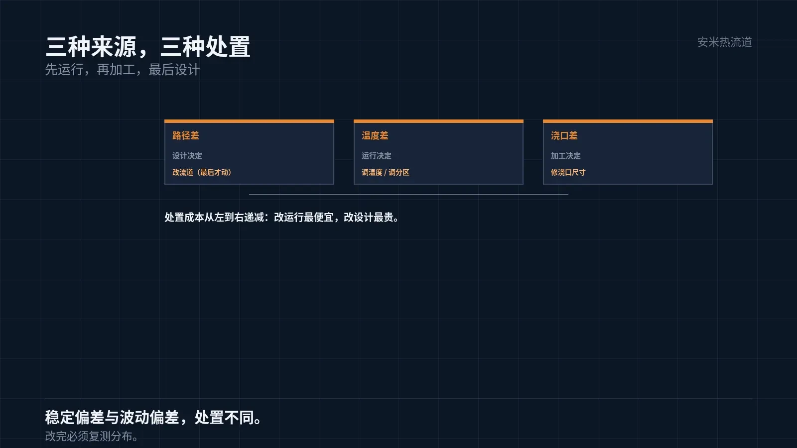
The first is "path difference." Variations in flow path lengths from each cavity to the split point cause differing pressure drops and melt input volumes.
The second factor is "temperature difference." Cavities with longer flow paths lose more heat, leading to lower temperatures and higher melt viscosity, which reduces melt input. Pressure drop and temperature effects are cumulative.
The third is "gate difference." Manufacturing tolerances cause variations in actual gate dimensions; smaller gates allow less melt input.
Among these three sources, path difference is determined by design, temperature difference by operation, and gate difference by manufacturing.
Follow this troubleshooting order: operation first, then manufacturing, and finally design. Operational parameters can be adjusted, manufacturing issues can be corrected, but design changes require mold modifications.
Natural vs. Artificial Balancing
Natural balancing uses runner geometry to ensure consistent cavity feed without parameter adjustments.
Artificial balancing corrects deviations by adjusting temperature settings or installing flow restrictors.
Natural balancing is stable and resistant to disruptions from material or parameter changes; artificial balancing is fragile and prone to deviation when parameters change.
Therefore, aim for natural balance during design: use symmetrical layouts, equal-length runners, and uniform gate sizes.
Use artificial balancing only when natural balancing is unachievable. Document the compensation extent, as it represents a potential risk.
Verification Methods
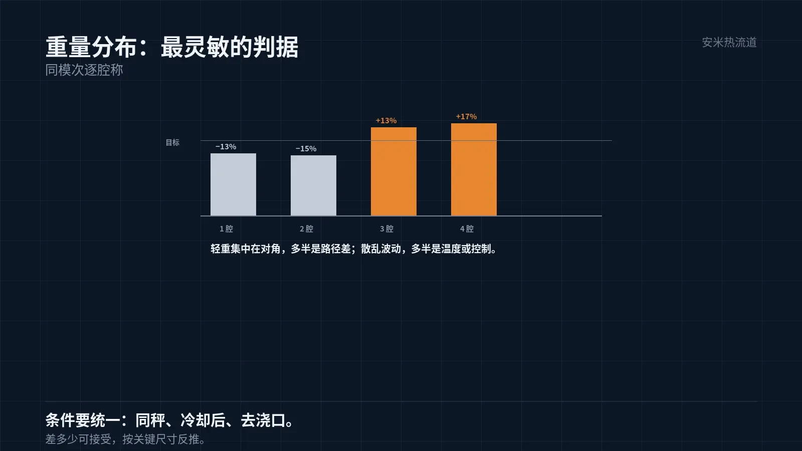
The first verification step is "same-shot weighing." Weigh each cavity part from the same shot individually and generate a distribution chart.
Step 2: Multi-shot weighing. Fire ten consecutive shots to determine if the deviation is stable or fluctuating.
Stable deviation suggests a design or machining problem; fluctuating deviation points to a temperature or control issue. Each requires a different corrective action.
Step 3: Gate Inspection. Verify that residue, stringing, and color are consistent across all cavity gates. Inconsistency indicates varying gate conditions.
Only after completing these three steps can you assess the mold's balance level. Inspecting a single part is insufficient to diagnose issues.
Interpreting distribution charts requires care. Focus on the shape, not just max/min values. A concave center with high ends indicates that specific cavities are significantly heavier or lighter.
A regular pattern indicates geometric causes; a scattered pattern suggests operational fluctuations. Each shape requires a different solution—mixing them leads to inaccurate diagnosis.
Multi-shot data requires a range chart. Calculate the difference between the maximum and minimum weight per shot and track how this range changes over time. Widening ranges indicate deteriorating conditions.
This step is often skipped, assuming one measurement is enough. However, single-point data cannot reveal trends, which are essential for deciding whether to intervene.
Modify or Not
If deviation is within tolerance, do not modify. Modifications introduce new variables where risk outweighs benefit.
If deviation exceeds limits but remains stable, first adjust operating parameters (temperature, holding pressure) to bring it within specification.
Only modify the runner or gate if it cannot meet standard. Calculate the required adjustment before making changes; do not rely on trial and error.
The calculation is based on the relationship between pressure drop and flow rate. The magnitude of flow rate differences caused by path and gate deviations can be estimated.
An exact value is not required, but an order of magnitude is needed. Trial-and-error gate adjustments often incur higher material and time costs than a single calculation.
Re-weighing after modification must use identical weighing conditions; otherwise, pre- and post-modification data are incomparable, rendering the modification ineffective.
Re-measurement also confirms that "this modification did not introduce new deviations." Since runners are interconnected, changing one area often affects another.
Weight distribution must be re-measured after modification. Without re-measurement, the effectiveness of the change is unknown.
Please provide the cavity count, part weight, current runner type, and weight distribution data. We will verify based on the runner design and issue a quotation upon confirmation.
MATCHED BY MATERIAL AND DEFECT
This article covers stringing, drooling, clogging, and high-heat resins; refer to SD for gate freeze and break-off.
Register for a selection review and quote
Submit part, mold, and material details. Our engineers will evaluate the gate solution per part and provide a quote.
Upload a 2D layout drawing using the form.
Online selection and quote
Scan to register