
Why Verify Injection Molding Machine Compatibility After Design?
工艺参数16 min read
On this page
When selecting, users often only verify mold compatibility with the hot runner, neglecting to check if the injection molding machine can supply it. Without adequate supply, even an optimal solution will fail to operate.
Match three values: shot volume, injection pressure, and clamping force.
Shot Volume
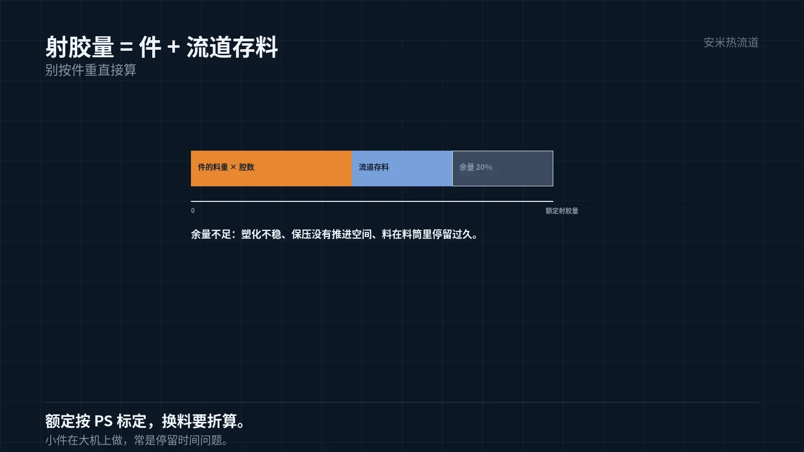
Shot volume must be sufficient, not just barely enough. The hot runner manifold holds material that does not enter the part but is drawn from the shot volume.
Therefore, required shot volume = part weight × number of cavities + manifold hold-up volume. Manifold hold-up volume is significant in multi-cavity molds.
The machine's rated shot volume is calibrated for PS. For other materials, convert using specific gravity and compression ratio.
Conversion uses barrel capacity × material factor. Incorrect factors cause overestimated or underestimated requirements.
In practice, actual demand should not exceed 80% of the rated shot volume. The 20% margin ensures plasticization quality and packing capability.
Insufficient margin leads to unstable plasticization. As the screw recovery distance nears its limit, plasticization time is compressed and melt uniformity is reduced.
Second, packing performance degrades. With shot volume at maximum, the screw has minimal forward travel during packing, which prevents effective pressure transmission to the cavity.
The third consequence is "excessive residence time in the barrel." With small shot sizes and small parts, material turnover in the barrel slows down, leading to degradation of heat-sensitive materials.
Therefore, matching requires not only "sufficiency" but also "turnover speed." Producing small parts on large machines often involves residence time issues rather than pressure issues.
Injection Pressure
Sufficient injection pressure is needed to push the melt to the end of each cavity.
Hot runner flow channels experience pressure drops. The longer the path, the narrower the channel, and the higher the material viscosity, the greater the pressure drop.
The rated pressure of an injection molding machine is calculated at the screw based on hydraulic principles. Pressure losses occur from the screw to the nozzle tip and vary with injection speed.
Therefore, "sufficiency" must be evaluated at actual injection speeds, not based on static parameters.
Assessment Method: Check for short shots. If the short shot end position is stable, there is sufficient pressure margin; if the position fluctuates back and forth, the pressure is at its limit.
Clamping Force
Sufficient clamping force is needed to counter cavity pressure. Insufficient force causes flash.
Required clamping force = Projected area × Average cavity pressure. The projected area must include all cavities and runners.
Hot runner channels are located within the mold cavity and generate pressure. In multi-cavity molds, the projected area of the runners cannot be ignored.
Average cavity pressure depends on material and part geometry. Thin-walled parts with long flow paths require higher pressure; thick-walled parts with short flow paths require lower pressure.
The clamping force margin accommodates fluctuations. Temperature and material variations cause pressure changes; without sufficient margin, flash occurs.

Screw and Plasticizing
Screw diameter and compression ratio must match the material. Use general-purpose screws for low-temperature materials and specialized screws for high-temperature materials.
LCP and PEEK are shear-sensitive; avoid excessive screw compression ratios to prevent degradation.
PEEK processing temperatures exceed 390°C, requiring adequate heating from the screw and barrel. Insufficient barrel heating prevents reaching the target temperature.
Plasticizing capacity must also be matched. If plasticization lags, cycle time increases, negating the hot runner's response advantages.
Therefore, "matching" involves more than three parameters—it also includes the screw and plasticization. All four factors must align for a proper match.
Another frequently overlooked factor is injection speed. Hot runner channels are narrow, so high injection speeds generate substantial shear heat, causing the melt temperature to exceed the setpoint.
Shear heat is especially significant at small gates. Increasing injection speed raises the actual gate temperature, causing stringing and drooling.
Therefore, the machine's injection speed capability must be considered during matching. Machines with excessively high speed limits require speed restrictions when used with small gates.
This explains why issues occur when switching machines using the same mold. While the mold stays the same, injection speed and shear conditions vary.
When switching machines, perform an "injection speed calibration": run short shots with identical parameters to verify that fill positions match. Discrepancies indicate differences in injection speed capabilities.
After calibration, record the maximum injection speed in the process documentation. This limit prevents excessive shear heat at the gate during operator or machine changes.
This is especially critical for LCP and PA46. These materials have narrow processing windows; a few degrees of excess shear heat can trigger degradation.
If degradation signs persist after reducing speed, stop adjusting on the machine. Instead, check gate dimensions and runner pressure drop.
Continuously tweaking "machine parameters" yields diminishing returns—the most common pitfall in high-temperature material setup. Parameter adjustment ranges are inherently narrow and produce no new results.
Barrel and Nozzle
The barrel must be retractable and properly aligned. Misalignment causes the nozzle to contact the sprue bushing off-center, resulting in leakage and stringing.
Nozzle type must match the gate. SD Series and valve gate nozzles feature different contact surface designs.
Nozzle temperature requires independent control. Relying on the main machine barrel zones is often insufficiently accurate.
This is especially critical for high-temperature materials. A temperature difference of just a few degrees at the nozzle can alter gate conditions.
Please provide part weight, number of cavities, material, current machine model, and screw specifications. We'll verify compatibility before sending your quote.
MATCHED BY MATERIAL AND DEFECT
This article covers stringing, drooling, clogging, and high-heat resins; refer to SD for gate freeze and break-off.
Register for a selection review and quote
Submit part, mold, and material details. Our engineers will evaluate the gate solution per part and provide a quote.
Upload a 2D layout drawing using the form.
Online selection and quote
Scan to register