
Steps from Hot Runner Installation to Qualified Parts
工艺参数17 min read
On this page
Mold installation and debugging require three steps: install, heat up, and trial run. Skipping intermediate steps leads to issues during mass production.
This article explains the process step by step, detailing what to do and verify at each stage.
Step 1: Cold State Inspection
Perform a cold-state inspection prior to installation. Verify the following: fit between the hot nozzle and gate bushing, hot nozzle verticality, manifold plate flatness, and wiring/connectors.
Use feeler gauges or bluing for fit checks. Uniform color indicates proper contact; uneven distribution indicates misalignment.
Measure verticality using a dial indicator. Deviation causes off-center pushing when hot, resulting in an off-center gate.
Cold-state inspections are often skipped because systems "look fine." However, cold-state issues are amplified in hot-state conditions.
Keep records from this step. Installation records serve as the baseline for future troubleshooting.
Another cold state check item is "hot nozzle protrusion length." Excessive protrusion causes the nozzle to push against the gate bushing, while insufficient protrusion leads to poor contact.
Measure protrusion length based on actual mold depth, not drawings. Machining tolerances may cause deviations from the drawings.
Another component is the thermal insulation layer. Inadequate insulation allows heat to transfer to the mold base under hot conditions, leading to slow heating and increased energy consumption.
Insulation must also be verified. Poor insulation between the heater and mold base can cause leakage current and temperature anomalies; measure this using a megohmmeter.
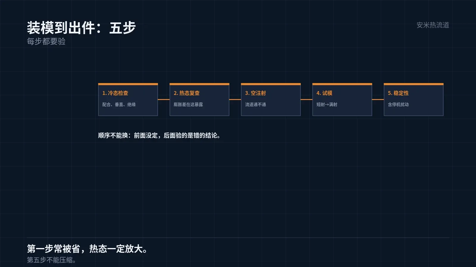
Step 2: Heating and Hot-State Reinspection
After cold assembly, heat to the operating temperature and hold until stable.
Once stable, perform a hot-state re-inspection: re-measure fits, verify alignment, and check for signs of material leakage.
Hot-state re-inspection is the most critical step in this process. This stage fully reveals geometric differences between cold and hot states.
If issues are found during re-inspection, cool down, disassemble, and modify. Then reheat and re-inspect. Do not proceed to trial molding until all issues are resolved.
This cycle is time-consuming but far less costly than line stoppages during mass production.
Step 3: Dry Shot and Runner Inspection
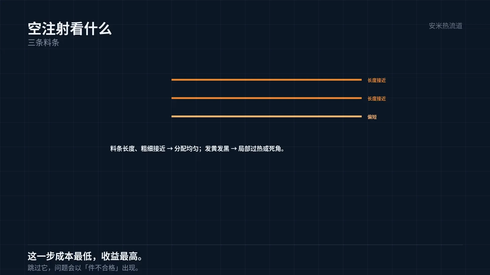
Once the temperature stabilizes, run a dry shot: inject material without opening the mold to verify smooth flow through the runner to the gate.
The dry shot checks for runner blockages, stagnant material, or degradation.
Signs of degradation include yellowing, blackening, or bubbling in the sprue. These indicate excessive local temperatures or dead spots.
During the dry shot, verify consistency across all cavities. Similar sprue lengths and diameters indicate uniform flow distribution.
This step identifies many issues early at low cost. Skipping it and proceeding directly to trial molding results in defective parts, making troubleshooting more difficult.
Step 4: Trial Molding and Parameter Setup
Trial molding sequence: Begin with short shots, gradually increase injection volume to full shots, then adjust holding pressure and cooling time.
Short shots help identify the flow front. Its position determines whether the runner and gate design are reasonable.
Record the progressive shot size increase. The levels where filling begins and flash appears define the process window.
Adjust holding pressure and cooling settings one parameter at a time. Changing three parameters simultaneously makes it impossible to identify the root cause of issues.
Retain trial molding samples, number them, and record parameters. These retained samples serve as the baseline for future comparisons.
Step 5: Stability Verification
After configuring parameters, run continuous production to verify stability—typically for hundreds to over a thousand cycles.
Verification items include key dimensional drift, gate cleanliness, temperature stability, and material leakage.
Perform disturbance testing: intentionally stop the machine for 10 minutes before restarting to verify that the first few cycles run normally. This simulates real production interruptions.
Failure in disturbance testing indicates a narrow process window, which can cause issues during mass production.
Completing all five steps marks the end of debugging. Skipping any step introduces risks for mass production.
The sequence of the five steps is fixed. Skipping the cold-state check can allow hot-state anomalies to obscure underlying cold-state issues, leading to confusion in later stages.
Perform dry-cycle injection before mold trials for the same reason: if the runner system is not clear, trial parts have no diagnostic value.
Stability verification comes last because it validates the conclusions from the previous four steps. Without completing the prior steps, verification is meaningless.
Stability verification also requires recording "defective shot counts." Note the shot that produced defects, along with the corresponding temperature and pressure.
These defective shots define the process window boundaries. Clear boundaries clarify the tolerance range for mass production.
Therefore, debugging outputs are not just "a set of parameters," but also "the tolerance range for fluctuations in those parameters." The latter is more critical.
Parameters with a defined tolerance range remain viable across shift changes, material batches, and seasons; parameters without tolerance ranges can only be adjusted by the debugger.
Common Time Allocation
In the five-step process, the time required for the first two steps is often underestimated. Cold and hot state inspections typically take one to two days.
Steps 3 and 4 involve adjustment, with duration varying by part and material. High-temperature materials typically require more time due to narrower process windows.
Step 5 is the "waiting" phase and requires a sufficient number of cycles. This stage cannot be compressed; doing so renders verification ineffective.
A sensible time allocation follows the principle: "Solidify the first two steps, detail the middle two, and patiently complete the final step." Otherwise, rework is often required.
Please provide the part geometry, material, number of cavities, and current process flow. We'll verify feasibility during mold installation and debugging, then issue a quote upon confirmation.
MATCHED BY MATERIAL AND DEFECT
This article covers surface gating or small precision parts; check TP for gate position and whether a dot mark is acceptable.
Register for a selection review and quote
Submit part, mold, and material details. Our engineers will evaluate the gate solution per part and provide a quote.
Upload a 2D layout drawing using the form.
Online selection and quote
Scan to register