
PEEK Nozzle Clogging: Impact of 395°C Melt vs. 170°C Mold
问题排查16 min read
On this page
PEEK clogs faster than other materials. With the same hot runner, PPS can be molded at a 150°C mold temperature, while PEEK is more prone to clogging even at higher mold temperatures of 170–200°C.
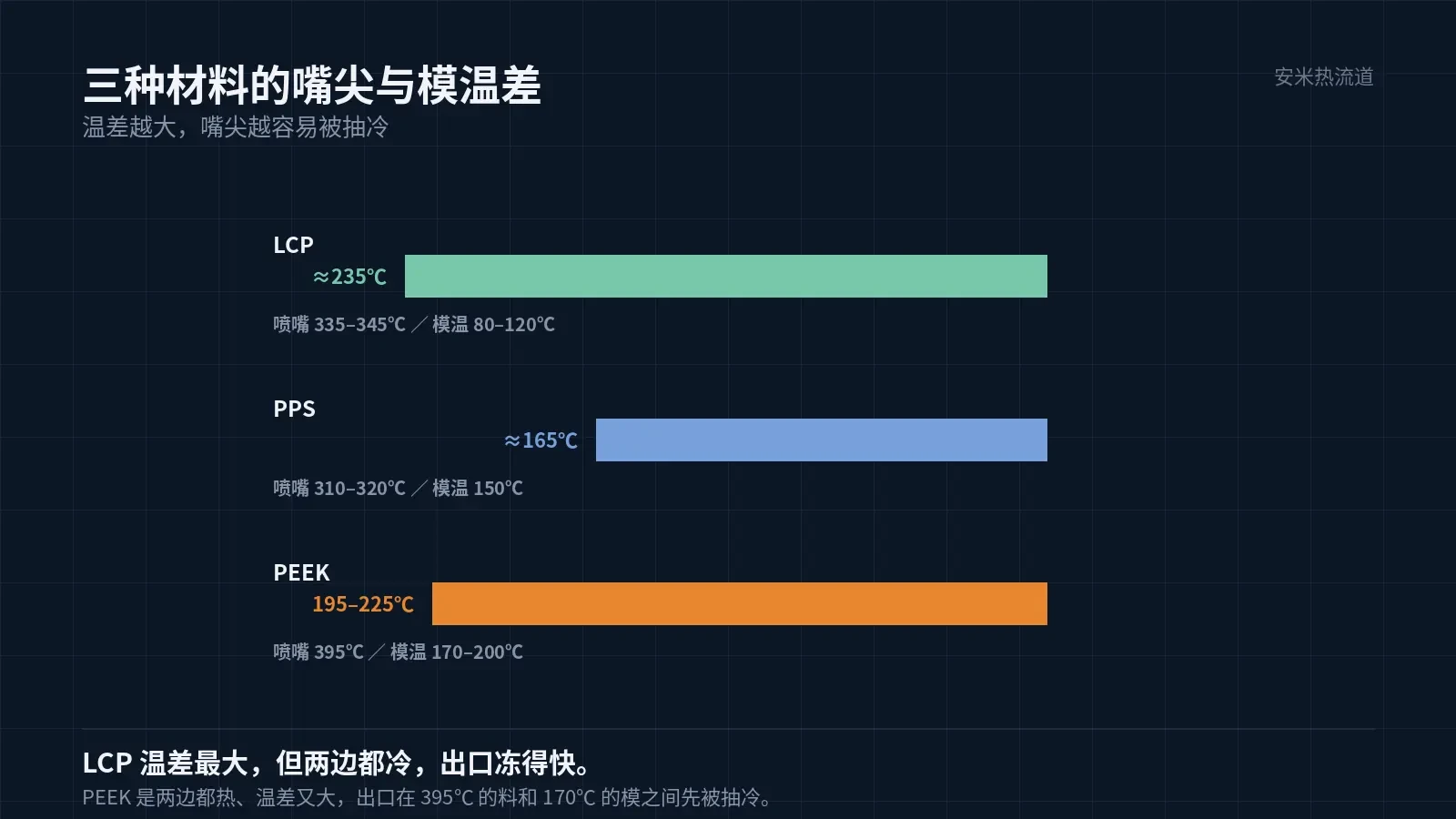
The issue is not low mold temperature, but a large temperature difference: a 395°C nozzle tip against a 170–200°C mold causes the most intense heat extraction.
Quantifying the Temperature Difference
For 650G, the nozzle is set to 395°C and the mold temperature ranges from 170°C to 200°C, resulting in a temperature difference of 195–225°C.
Comparison with two others: LCP at 335–345°C vs. 80–120°C (difference 230–240°C); PPS at 310–320°C vs. 150°C (difference approx. 165°C).
Temperature difference isn't the only factor, but it determines how quickly heat dissipates from the nozzle tip to the mold. PEEK operates at the highest absolute temperature, resulting in the most severe heat loss; the gate exit is where the temperature first drops.
Additionally, a higher mold temperature reduces the differential and lowers clogging risk. The values for PEEK (170°C), HT (190°C), and ST (200°C) are not arbitrary; different grades have distinct crystallization requirements.
As stated directly on the material datasheet: pairing 395°C with 170–200°C creates the largest temperature differential among the five materials, resulting in the highest clogging risk.
Why does it cool down at the exit first?
The nozzle tip has low thermal capacity, causing heat to flow from the tip to the mold and positioning the gate exit at the forefront.
PEEK's melting point is 343°C. If the gate exit falls below 343°C, the material begins to solidify. Due to PEEK's high melting point, a similar temperature drop causes it to enter the solidification zone sooner.
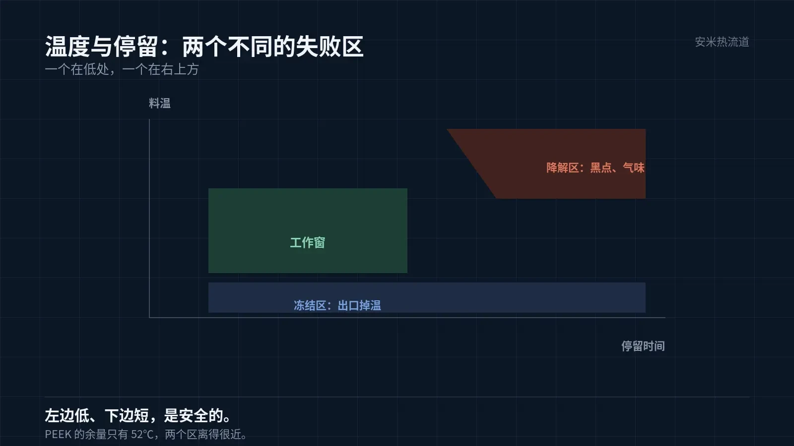
Dropping from 395°C to 343°C leaves only a 52°C margin. This is the smallest margin among the five materials. A slight temperature drop at the gate exit causes solidification, making PEEK most sensitive to nozzle tip heating compensation.
Symptoms: Consistent molding suddenly fails in one cavity. After disassembling the nozzle tip, a segment of hard material with normal color and no burn marks is found.
This clogging type requires heating compensation and shortened heat dissipation paths—not carbon cleaning. Misdiagnosis leads to recurrence even after repeated cleaning.
Two heating compensation methods: 1) Independently increase the nozzle tip temperature setting, or 2) Reduce the contact area between the nozzle tip and the mold. Adjust the settings before modifying the structure.
Another cause of clogging is degradation.
PEEK degrades above 400°C. The barrel heating system must reach 400°C, and HT/ST grades require 430°C to cover this high-temperature range.
Degradation-related clogging appears as black spots, brown streaks, and foul odors upon removal. The material becomes brittle instead of tough.
A hidden degradation pathway involves material change and machine cleaning. Changing PEEK colors requires purging compounds; if these compounds remain at 395°C for too long, they carbonize and leave residue in the flow channels that reappears upon restart.
The remediation approaches for the two clogging types are opposite: freezing requires adding heat and minimizing heat loss, while degradation requires lowering temperature and reducing residence time. Misdiagnosis worsens the problem when heat is added.
Three On-Site Steps
First, measure the nozzle tip temperature. A setpoint of 395 does not equal an outlet temperature of 395; the difference determines whether to add heat or reduce temperature.
Second, inspect the heater bands and thermocouples. Due to high temperatures with PEEK, these components age more quickly; it is common for panel readings to appear normal while actual temperatures are lower.
Third, check residence time. Waiting for material, shutdowns, and mold changes all add to residence time; prolonged exposure at high temperatures increases PEEK degradation.
After completing the three steps, determine the direction: if color is normal, increase heat; if black specks appear, reduce temperature.
Record keeping is essential: log the clogging time, settings at that moment, shutdown duration, and findings upon disassembly. After two months of data collection, you can determine whether the issue stems from heater band degradation or a process problem. Without records, every incident requires guessing from scratch.
Adjustable vs. Non-adjustable Parameters
Adjustable: Nozzle tip heating, heater bands and thermocouples, gate dimensions, valve pin timing, and residence time.
Non-adjustable: Do not lower the mold temperature. The 170–200°C range is optimized for crystallization; reducing it compromises dimensional stability and performance without reliably resolving nozzle clogging.
Do not increase the melt temperature. At 395°C, the material is already near its upper limit; further increases risk degradation, creating new issues to replace existing ones.
The alternative is to reduce residence time. Schedule PEEK production consecutively to avoid repeated heating and cooling cycles between low-temperature materials, as each material change increases high-temperature residence time.
Rule of Thumb for Diagnostics
Clean, hard material with normal color indicates freezing; focus on supplemental heating and minimizing heat dissipation paths.
Black specks and strong odors indicate degradation; focus on reducing temperature and shortening residence time.
If inspection shows no blockage but parts are still short-shot, check venting and gates first; do not assume nozzle clogging. Parts with trapped gas exhibit burn marks or gas traces, while nozzle tips remain clean.
For PEEK nozzle clogs, first measure temperature differentials to distinguish between freezing and degradation. This determines the corrective action.
Please provide the material grade, measured nozzle tip temperature, and downtime records. We will verify the outlet temperature and residence time, then submit a quote once the solution is confirmed.
Estimate residence time by dividing the melt volume in the flow channel by the shot size; do not rely on intuition to judge duration.
The calculated value is an average; actual residence times vary. Check for stagnant zones in the flow channels, as averages can mask dead spots.
MATCHED BY MATERIAL AND DEFECT
This article covers stringing, drooling, clogging, and high-heat resins; refer to SD for gate freeze and break-off.
Register for a selection review and quote
Submit part, mold, and material details. Our engineers will evaluate the gate solution per part and provide a quote.
Upload a 2D layout drawing using the form.
Online selection and quote
Scan to register