
PA6T Nozzle Clogging at Small Gates: Mold Temp 140°C Analysis
问题排查16 min read
On this page
PA6T nozzle clogging typically occurs at small gates. With gate diameters in the tenths of a millimeter range, a single clog can halt the entire mold.
Counterintuitively, freezing occurs even though mold temperatures exceed 140°C, where outlet freezing should be unlikely.
Three Clogging Types: Initial Diagnosis
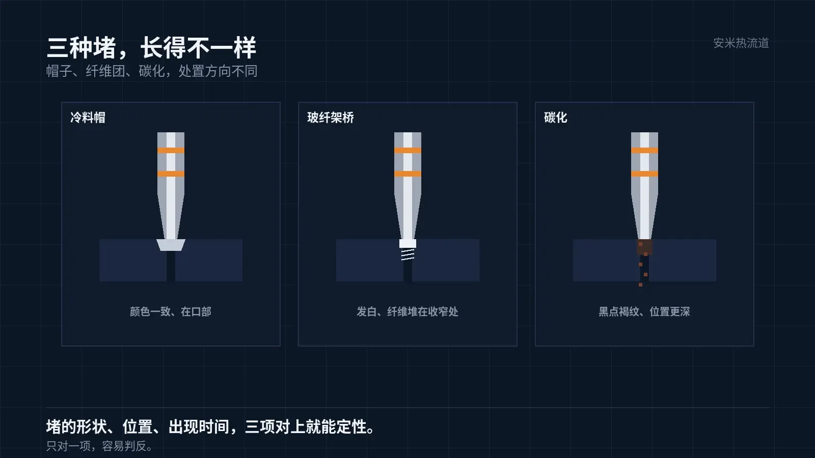
The first type is cold slug formation. A solidified layer forms at the gate, thickening until it blocks the channel. After removal, it appears as a cap matching the body color.
The second type is glass fiber bridging. Fibers accumulate at the narrowed gate section, forming a mesh that blocks material flow and increases pressure. Removing the blockage reveals whitish fiber clumps.
The third type is carbonization. Extended exposure to high temperatures causes discoloration and carbon buildup, which may block areas deeper than the gate opening. Affected parts exhibit black spots, brown streaks, and a burnt odor.
Remediation strategies vary: cold slugs need heat compensation; bridging requires gate modification and better fiber dispersion; carbonization demands reduced residence time. Mixed approaches worsen the issue.
A fourth field condition is air trapping. Inadequate venting causes backpressure at the gate, blocking material entry and producing symptoms similar to nozzle clogging. The distinction is burn marks or flow lines on the parts while the gate remains clear upon inspection.
Temperature Differential Analysis
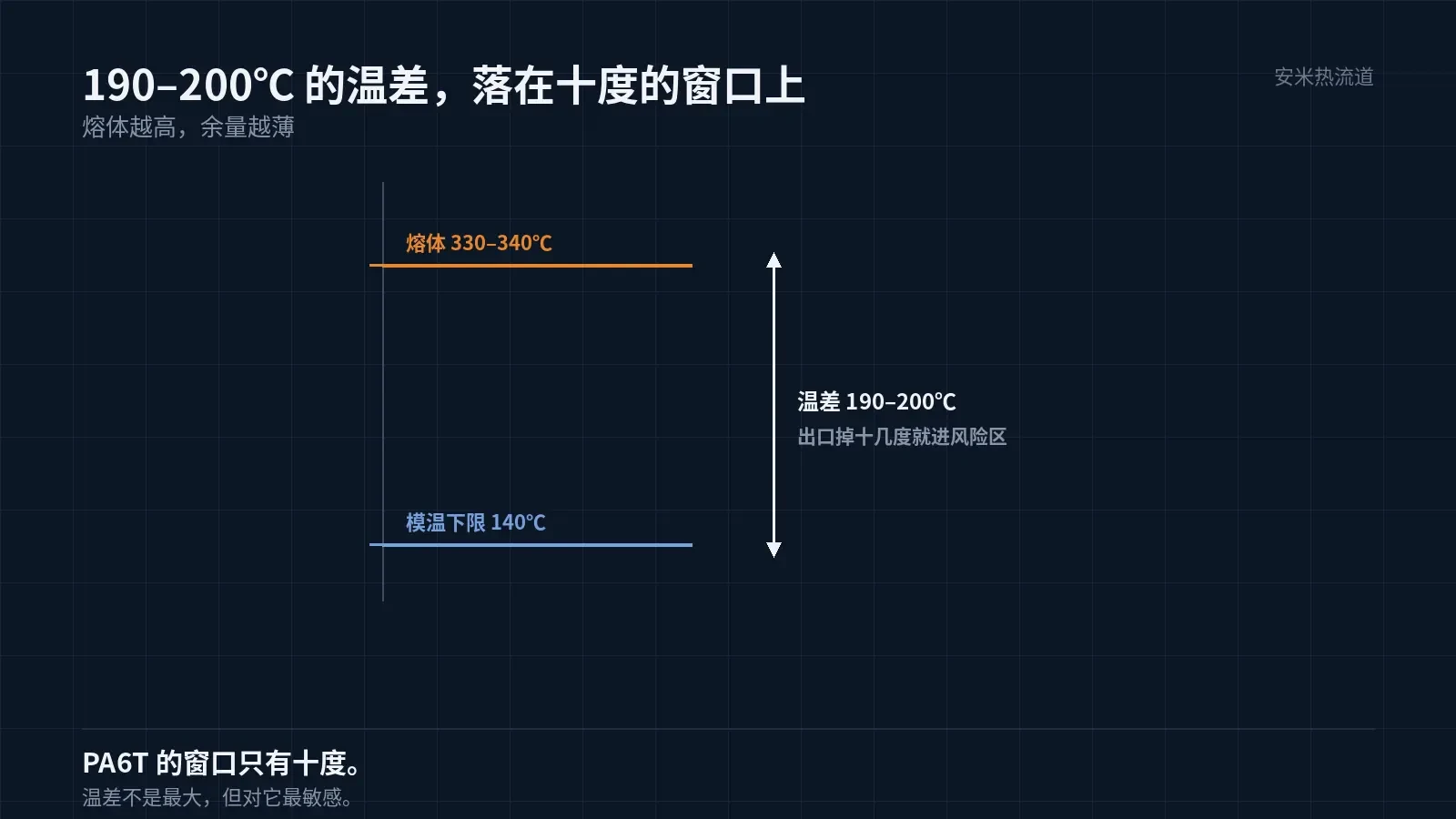
PA6T melt temperature is 330–340°C, with mold temperature no lower than 140°C. The resulting temperature difference is approximately 190–200°C.
This temperature differential is not the largest among the five materials; PEEK ranges from 195 to 225°C. However, PA6T has a narrow 10°C window: an exit drop exceeding 10°C causes issues, making it more sensitive to temperature variations.
A mold temperature of 140°C is critical for crystallization and dimensional stability, not for preventing clogging. Using it as an anti-clogging measure is misguided; its primary role is to regulate the heat extraction rate from the gate within a specific range.
Why small gates fail first
Smaller gates have smaller flow channel cross-sections; under the same heat flux density, the gate tip cools faster.
Smaller gates produce higher shear rates and greater shear heating. Since shear heating and heat dissipation occur simultaneously at the gate exit, this location exhibits the highest temperature instability.
Smaller gates make it easier for glass fibers to accumulate at the constriction. For glass-filled materials, bridging is significantly more likely with small gates than with large ones.
For this material group in small-gate molds, nozzle clogging is a routine risk, not an occasional one. Gate dimensions and material selection must be validated together during the design phase.
Three actions during the design phase: avoid extreme minimum gate sizes, incorporate transitions at the gate entry, and provide sufficient venting depth based on the material. Implementing these once in the mold is cheaper than fixing them a hundred times in production.
Diagnostic Methods
Inspect the clog shape: hat-shaped with uniform color indicates a cold slug; white fibrous mass indicates bridging; black spots or brown streaks indicate carbonization.
Inspect clog location: outermost layer at the gate suggests heat dissipation issues; deep within the channel indicates residence time issues.
Check timing: clogging after a few shots at startup indicates cold slug; clogging after several hours of production suggests carbonization or bridging.
Combining these three factors enables basic qualitative diagnosis. Relying on just one factor often leads to incorrect conclusions.
Standardize recording methods: For the same machine and mold, log clogging time, current settings, and removed nozzle tip condition on a single card. One shared card across three shifts is more effective than three separate notebooks.
Additional diagnostic step: Replace with a new nozzle tip. If the clog location shifts, the issue is in the gate or mold; if it remains unchanged, the problem lies in the material or temperature. This method significantly reduces troubleshooting time.
Remediation Sequence
1. Increase the nozzle tip temperature by one step and observe whether the clogging interval extends. If it does, supplemental heating is effective.
2. Verify actual gate dimensions. Drawing specifications do not guarantee manufactured sizes; wear, polishing, and repairs alter dimensions.
3. Reduce dwell time. Include mold changes, material waiting, and downtime. PA6T carbonizes faster when residence times exceed 330°C.
4. Check venting. Inadequate venting creates air pressure at the gate that blocks material flow, mimicking clogging but actually being caused by air resistance.
5. Only adjust gate dimensions or switch gate types if earlier steps fail. This is the final step, not the first.
When modifying gates, verify three factors: shear rate, effective holding pressure length, and gate mark. Changing diameter without adjusting length may not reduce shear; failing to check marks after modification risks cosmetic defects.
Two Boundaries
Do not rely solely on increasing melt temperature. Higher temperatures accelerate carbonization and may increase clogging frequency.
Do not use steel wire for cleaning. Scratches on the small gate's inner walls can snag glass fibers, accelerating future clogs. Use dedicated cleaning agents or perform disassembly and inspection to clear the channel.
Additionally, do not use open flame to heat machine gates. Localized fast heating disrupts the thermal fit between the nozzle tip and gate; although it may appear clear temporarily, it leads to faster clogging in the next shift.
Please provide the gate dimensions, clogging shape, and time from startup to clogging. We will evaluate each category separately and provide a quote once the solution is confirmed.
Track cleaning logs. Session counts and material usage per clean help determine the actual load on flow channels.
If load is high, check the cleaning method first, then the material. The method is adjustable; the material is fixed.
MATCHED BY MATERIAL AND DEFECT
This article covers stringing, drooling, clogging, and high-heat resins; refer to SD for gate freeze and break-off.
Register for a selection review and quote
Submit part, mold, and material details. Our engineers will evaluate the gate solution per part and provide a quote.
Upload a 2D layout drawing using the form.
Online selection and quote
Scan to register