
Multi-Cavity Mold Temperature Variance: Why Center is Cold and Edges Hot?
工艺参数18 min read
On this page
In a 16-cavity mold, parts from different cavities exhibit dimensional variations. Investigation revealed uneven mold temperatures: central cavities were 5°C lower, while outer cavities were 5°C higher.
A 5°C difference may seem minor, but for a 0.05mm tolerance, it can significantly reduce yield. This article explains the sources of this temperature variance.
First, verify that a temperature difference exists.
Mold temperature is not the value shown on the temperature controller. The controller displays inlet and outlet water temperatures, which differ from the actual cavity surface temperature.
To determine the true temperature of each cavity, measurement is required. Three methods are available: infrared thermometer, embedded thermocouple, and in-mold pressure/temperature sensor.
An infrared thermometer measures surface temperature at mold opening. It is fast but prone to environmental interference and inaccurate, making it suitable only for rough assessments.
Embedded thermocouples measure temperature at specific internal mold points with higher accuracy. However, they require drilling holes into the mold, making modifications cumbersome.
In-mold sensors deliver the highest accuracy by measuring both cavity surface temperature and pressure. They are costly and typically used in precision molds.
Each method has its use: employ infrared for routine troubleshooting, thermocouples for verification, and in-mold sensors for precision components. Do not treat infrared data as definitive.
Measurement timing is also critical. Temperatures vary at mold opening, after ejection, and during cooling. Ensure comparisons are made at the same time point.
Record the cavity, time point, location, and temperature after measurement. Stating only "the center is lower" is meaningless and provides no actionable information.

Center cooled, edges heated due to cooling water circuits
Mold cooling water circuits typically feature a main inlet and branch outlets. The center cavity circuit is closer to the main line, while edge cavity circuits are farther away.
Longer circuits create longer flow paths and greater heat absorption, resulting in higher water temperatures at edge cavities. Elevated water temperatures reduce cooling efficiency and increase mold temperature.
This seems counterintuitive: because water absorbs more heat in edge cavities, the mold temperature should be lower. In practice, however, longer circuits have reduced flow rates, leading to inefficient heat removal and higher mold temperatures.
Therefore, the core issue is not water temperature but flow distribution. Resistance from the main line to each branch varies, leading to uneven flow rates.
The solution is to add flow distributors and control valves to enable adjustable flow for each branch. Adjust based on measured cavity temperatures, not theoretical calculations.
This must be addressed during new mold design. Adding flow distributors after mold completion often lacks sufficient space.
Lock the regulating valves after adjustment to prevent unauthorized changes in the workshop. The adjusted flow distribution is the process baseline for this mold; any change will disrupt it.
Manifold selection must also account for pressure drop. The manifold itself introduces resistance; excessive pressure drop affects flow across all branches.
Calculate this during mold design: subtract the mold pressure drop from the pump head to determine the available differential pressure for each branch.
Monitor return water temperature. If the return temperature exceeds the inlet by more than 5°C, flow is insufficient and heat removal is failing.
This check is easiest to perform on-site but is often overlooked. A single thermometer can reveal whether the water circuit is clear.
Another factor: water cleanliness. Scale buildup in water lines reduces flow and increases temperature variance year over year. Establish water quality standards and descaling schedules.
The hot runner causes temperature fluctuations.
In multi-cavity hot runners, nozzle temperature setpoints may be identical, but actual temperatures can vary.
Nozzle temperature is affected by the mold temperature. Central nozzles, surrounded by hot molds, lose heat slowly and run hotter; edge nozzles, near the mold frame, lose heat quickly and run cooler.
Higher nozzle temperature reduces melt viscosity, accelerates filling, and produces heavier parts with larger dimensions; lower nozzle temperature slows filling, resulting in lighter parts with smaller dimensions.
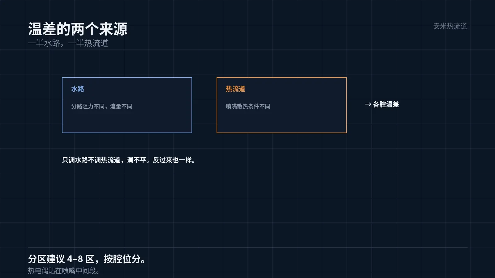
Cavity temperature differences are caused equally by water channels and the hot runner. Adjusting only the water channels, without adjusting the hot runner, cannot equalize temperatures.
Hot runner zones must be separated by cavity position; nozzles cannot share a single zone. Center and edge zones require independent temperature control, with setpoints adjusted based on actual measurements.
More zones aren't always better. Too many zones can cause thermocouple interference and destabilize temperature control. Typically, 4–8 zones are used.
Impact of Mold Material and Design
Mold steel has limited thermal conductivity. Using different materials for cavities and cores affects heat transfer. Cores often incorporate beryllium copper or inserts to improve thermal performance.
Mold thickness also impacts performance. Thick mold bases dissipate heat slowly, making it difficult for center cavities to release heat; thin mold bases dissipate heat quickly, resulting in smaller temperature differences.
Insert contact surfaces impact thermal conduction. Poor machining of insert-mold base interfaces creates air gaps, reducing thermal conductivity and leading to higher temperatures in the cavity.
These structural factors can be detected via temperature measurement but require mold modification to correct. Therefore, thermal paths must be considered during design.
In multi-cavity mold design, heat conduction paths must be symmetrical. Asymmetry prevents effective balancing through parameter adjustment.
Verification: Measure each cavity individually
Group 1: Run water through the empty mold and measure cavity temperatures to check for temperature differences. Group 2: Perform molding shots and measure part weight and critical dimensions per cavity. Group 3: Run 200 consecutive cycles to monitor drift in temperature differences.
Combining data from all three groups clarifies whether temperature differences stem from structural issues or parameter settings. Parameter adjustments do not resolve structural issues.
Please provide the number of cavities, set mold temperatures, measured temperatures per cavity, and part weight variations. We will verify the cooling circuit and hot runner zones before issuing a quote.
MATCHED BY MATERIAL AND DEFECT
This article covers surface gating or small precision parts; check TP for gate position and whether a dot mark is acceptable.
Register for a selection review and quote
Submit part, mold, and material details. Our engineers will evaluate the gate solution per part and provide a quote.
Upload a 2D layout drawing using the form.
Online selection and quote
Scan to register