
Why Can't Naturally Balanced Runners Fill All Cavities Evenly?
工艺参数17 min read
On this page
Runner systems in multi-cavity molds come in two types: naturally balanced and artificially balanced. Natural balance uses geometric symmetry to ensure equal flow length for each cavity, while artificial balance uses throttling to ensure equal resistance for each cavity.
Many assume that achieving natural balance solves all problems. That's not true. This article explores the limits of natural balance.
Natural balance equalizes length, not temperature.
In a naturally balanced runner system, each cavity has the same flow length. Theoretically, pressure loss is equal across all cavities, ensuring consistent filling.
However, equal flow length does not mean equal temperature. Even though melt residence time in the runners is identical, heat dissipation conditions vary.
Runners near the mold frame dissipate heat faster, leading to lower melt temperatures; runners surrounded by the mold dissipate heat slower, resulting in higher melt temperatures. These temperature differences cause varying viscosities and inconsistent filling.
Therefore, natural balance addresses "geometry" but not "thermal" factors.
Another overlooked factor is shear heating. As the melt flows through the runners, it generates heat due to shear; areas with higher flow rates experience greater temperature rises.
In a naturally balanced runner system, flow rates vary across branches. Higher-flow branches generate more heat, exhibit lower viscosity, and fill faster; lower-flow branches generate less heat and fill slower.
This factor is especially critical in multi-cavity molds: the more cavities, the greater the thermal non-uniformity.

Manual balancing via throttling compensation
Manual balancing requires adding throttle valves to branch runners or adjusting runner diameters to regulate resistance for each cavity.
Adjustments are based on part weight. Reduce resistance for lighter parts; increase it for heavier ones.
Adjust incrementally. Excessive changes disrupt balance. Adjust by 5–10% per step, then measure after molding.
Throttle valve adjustment range is limited. If runner diameter differences are too large, throttling cannot compensate; modify the runner instead.
Note that throttling increases shear. High shear raises melt temperature and reduces viscosity, improving fill. This effect masks throttling resistance and must be accounted for during adjustment.
Manual balancing combines increased resistance and temperature rise. Inexperienced operators may worsen the imbalance with improper adjustments.
Balancing sequence: First, check the flow front using short shots. Next, weigh the parts. Finally, adjust dimensions. Skipping steps will lead to inaccurate results.
After adjustment, record the following settings: valve opening, cavity part weight, and ambient temperature. This establishes a baseline for future mold or material changes.
Another phenomenon: part dimensions change after balancing. This occurs because filling behavior and pressure transmission during packing have changed.
Balance in two steps: first equalize fill, then adjust dimensions. Mixing these steps causes confusion.
Archive short-shot test photos. Flow front shapes reveal issues: a significantly slower cavity indicates high resistance; a faster one indicates an oversized gate.
If a cavity consistently fills last and valve adjustment has no effect, inspect the gate. It may be undersized due to machining errors.
Gate machining errors are critical for micro parts. A 0.02mm deviation on a 0.2 mm gate causes a 10% flow difference.
Machine gates via wire EDM or precision grinding, not standard milling. Insufficient accuracy prevents proper balancing.
Regularly inspect gates for wear. Enlarged gates increase flow and leave part gate vestiges.
Photo comparisons are more intuitive than data. Use archived photos to evaluate changes during mold repair.
For short-shot tests, ensure accurate shot volume. Volume errors distort flow front analysis.
Runner Diameter Effect
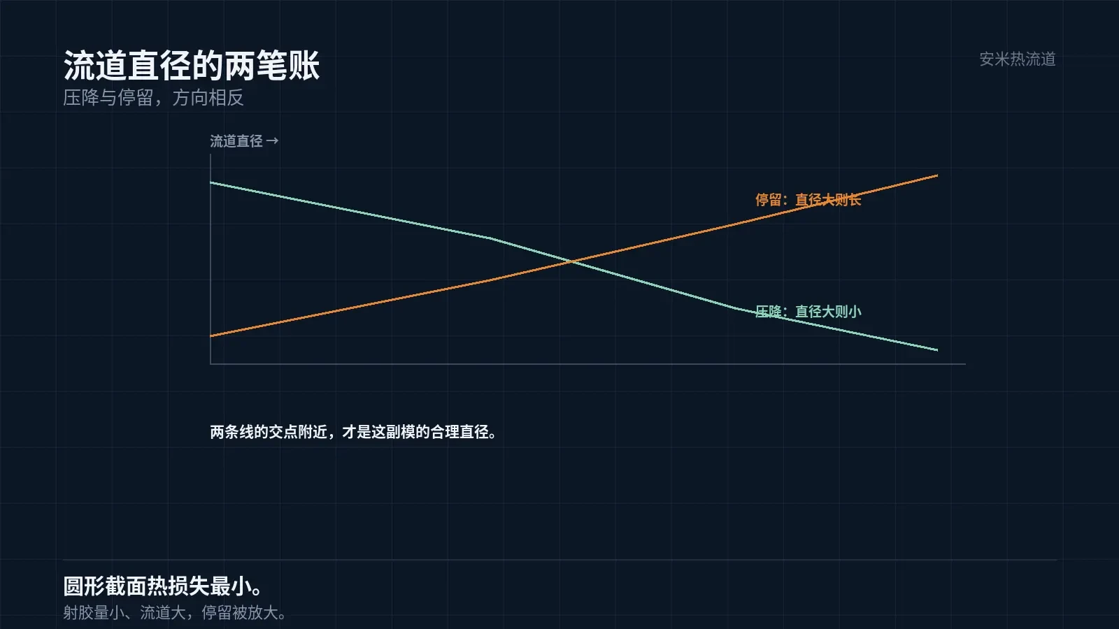
A larger runner diameter reduces pressure loss and improves filling; a smaller diameter increases pressure loss and hinders filling.
For multi-cavity molds, size the runner diameter based on total shot volume: large volumes require larger runners; small volumes require smaller runners.
If the runner is too small, high pressure drop prevents complete filling at the end; if it's too large, long residence time causes degradation. Both factors must be balanced.
The runner's cross-sectional shape also matters. Circular runners have the smallest surface area and minimal heat loss, while trapezoidal and rectangular runners have larger surface areas and greater heat loss.
Therefore, for the same cross-sectional area, circular runners fill more effectively. Select this option during runner design.
Melt Front Position Is a Better Indicator Than Pressure
To assess cavity balance, monitor the melt front arrival time. If all cavities fill simultaneously, the system is balanced.
Two measurement methods are available: short shot testing and in-mold sensors. Short shot testing is cost-effective: run several shots with varying injection volumes to observe the fill ratio of each cavity.
In-mold sensors are accurate and can measure the pressure curve for each cavity. However, their high cost limits them to precision molds.
Short Shot Test Procedure: Set injection volume to 60%, 80%, and 95%. Run multiple shots at each setting and verify the fill status of each cavity.
If a cavity is fully filled at 60%, it indicates low resistance; if some cavities remain unfilled at 95%, it indicates high resistance.
Following this test, cavity differences are quantified to guide runner balancing or flow control adjustments.
Verification: Short Shot + Part Weight + Dimensions
First set (short shot): Use three-stage injection volumes to track the flow front. Second set (part weight): Weigh parts from each cavity; balance is achieved if differences are within 2%. Third set (dimensions): Measure key dimensions across cavities to analyze distribution.
After completing these three sets, you can determine runner balance. For unbalanced systems, adjust flow control first; if that fails, modify the runner.
Send us the number of cavities, runner type, part weight per cavity, and short shot photos. We will verify runner balancing before providing a quote.
MATCHED BY MATERIAL AND DEFECT
This article covers surface gating or small precision parts; check TP for gate position and whether a dot mark is acceptable.
Register for a selection review and quote
Submit part, mold, and material details. Our engineers will evaluate the gate solution per part and provide a quote.
Upload a 2D layout drawing using the form.
Online selection and quote
Scan to register