
Why Do Weld Lines Break More Easily as Glass Fiber Content Increases?
工艺参数16 min read
On this page
Parts may fracture along a specific line, typically the weld line. Verify the material: higher glass fiber content can weaken weld lines. This is an expected outcome.
This article explains why weld lines are weak and how to restore their strength.
Two melt fronts meet; glass fibers fail to interlock.
A weld line forms where two melt fronts converge. At this point, both melt streams have cooled and pressure has dropped.
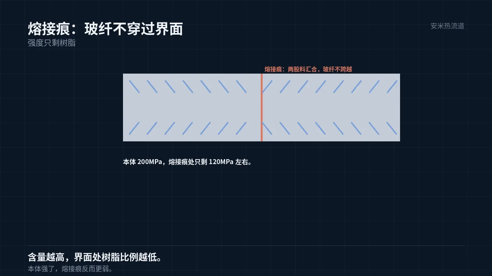
Glass fibers are rod-shaped. When two melt streams meet, the fibers at the interface align face-to-face instead of overlapping. No fibers cross the interface; only resin is present.
Therefore, weld line strength depends on resin strength, not composite strength. Higher glass fiber content reduces the resin fraction at the interface, weakening the weld line.
This difference is evident in tensile tests: for a material with a bulk strength of 200MPa,, the weld line strength may be as low as 120MPa..
Increasing glass fiber content from 30% to 50% boosts bulk strength but reduces weld line strength. This is a common trade-off in high-glass-fiber parts.
Another key factor is weld line width. If pressure is insufficient when the melt streams converge, the material at the interface remains uncompacted, creating a visible weld line with reduced strength.
Weld line width depends on the convergence angle. Melt streams colliding head-on create a wide weld line, while angled convergence produces a narrow one. Gate angle affects the convergence angle.
Weld line location is determined by the gate
Weld lines do not appear randomly. They form where two melt fronts meet: around holes, near inserts, at multi-gate convergence points, and at the ends of long parts.
Adjusting the gate position shifts the weld line location. Therefore, specifying the gate during the design phase effectively determines where the weld line will form.
Keep it simple: place weld lines in non-load-bearing areas. Load-bearing zones include snaps, pivots, pins, and regions around bolt holes.
If load-bearing areas cannot be avoided, reinforcement is required. Use one of three methods: increase weld line strength, modify the structure, or change the material.
Methods to improve weld line strength are discussed below. Structural modification involves relocating the load point, while material modification reduces glass fiber content.
Four measures to strengthen weld lines
The first measure is increasing the mold temperature. A higher mold temperature leads to a higher melt temperature at convergence, promoting sufficient molecular chain diffusion and stronger interfacial bonding.
The second method is to increase injection speed. Higher speeds help maintain melt temperature at the convergence point, strengthening the interface. However, high speeds also induce shear and orientation.
The third method is venting. Gas at the junction separates the interface, significantly reducing strength. Effective venting ensures a solid bond.
The fourth method is gate location. Position weld lines where ribs or thick-wall supports exist to compensate for strength through geometry.
Among these four methods, mold temperature and venting are the most effective and cost-efficient. Injection speed and gate location require changes to both parameters and molds, resulting in higher costs.
Can all four methods be used simultaneously? In most cases, yes. Combining high mold temperature, fast injection speed, proper venting, and optimal gate location can restore weld line strength to over 70% of the base material.
The 70% value is empirical; actual results vary significantly by material and structure. Determine specific values through sample testing rather than applying this rule universally.
Another less common method is localized heating. Inserting heater rods near the weld line raises the temperature at the convergence point. This technique is used in precision molds.
Localized heating increases mold complexity and energy use. It is cost-effective for high-volume small parts but not economical for low-volume large parts.

Weld Line Acceptance Criteria
Weld line strength cannot be determined by visual inspection. Visual checks only reveal whether the mark is visible, not its strength.
Two acceptance methods are available: whole-part destructive testing and local sampling. Whole-part testing requires breaking the part to inspect the fracture location; local sampling involves cutting a strip from the weld line for tensile testing.
Whole-part testing is simple but qualitative only. Local sampling is accurate but destructive and costly.
In production, the standard practice is "local sampling for first-article inspection and spot checks of whole parts for mass production." This approach enables both quantitative measurement and process monitoring.
Sampling direction is critical. Strength varies depending on whether samples are taken parallel or perpendicular to the weld line. Standards must clearly specify this.
Records must specify weld line locations. Weld line strength varies by position within the same part; reporting only an average value is meaningless.
Another metric is weld line appearance. For cosmetic parts, weld lines must be invisible—this depends on mold temperature and injection speed, not material selection.
Appearance and strength often conflict: high mold temperature improves surface quality but extends cycle time; low mold temperature reduces cycle time but compromises appearance. Trade-offs must be determined based on the part's application.
Design Guidelines for High-Glass-Fiber Components
First, minimize weld lines. Fewer gates and smoother flow paths reduce the number of weld lines.
Second, weld line locations must be predictable. Use mold flow analysis to predict them and review the results during design.
Third, avoid weld lines in load-bearing areas. If unavoidable, reinforce with ribs, thicker walls, or inserts.
Fourth, clearly define acceptance criteria. Specify allowable strength loss at weld lines on drawings or technical agreements.
Following these four points ensures reliability for high-glass-fiber parts. Ignoring them causes persistent breakage during mass production.
Submit the part drawing, gate layout, glass fiber content, and load positions. We will verify weld lines and reinforcements before providing a quote.
MATCHED BY MATERIAL AND DEFECT
This article covers surface gating or small precision parts; check TP for gate position and whether a dot mark is acceptable.
Register for a selection review and quote
Submit part, mold, and material details. Our engineers will evaluate the gate solution per part and provide a quote.
Upload a 2D layout drawing using the form.
Online selection and quote
Scan to register