
Gate Location: Why "Easy Feeding" Is Not Enough
工艺参数17 min read
On this page
When evaluating gate location, the most frequent feedback is "this spot feeds well." Good feeding stems from mold design, not part geometry. Part-related factors include flow path, weld lines, orientation, and venting.
This article covers four gate location constraints and how to distribute multi-point gating.
First Constraint: Flow Ratio
The flow ratio is the distance from the gate to the farthest point in the cavity divided by the wall thickness. A higher flow ratio makes filling more difficult.
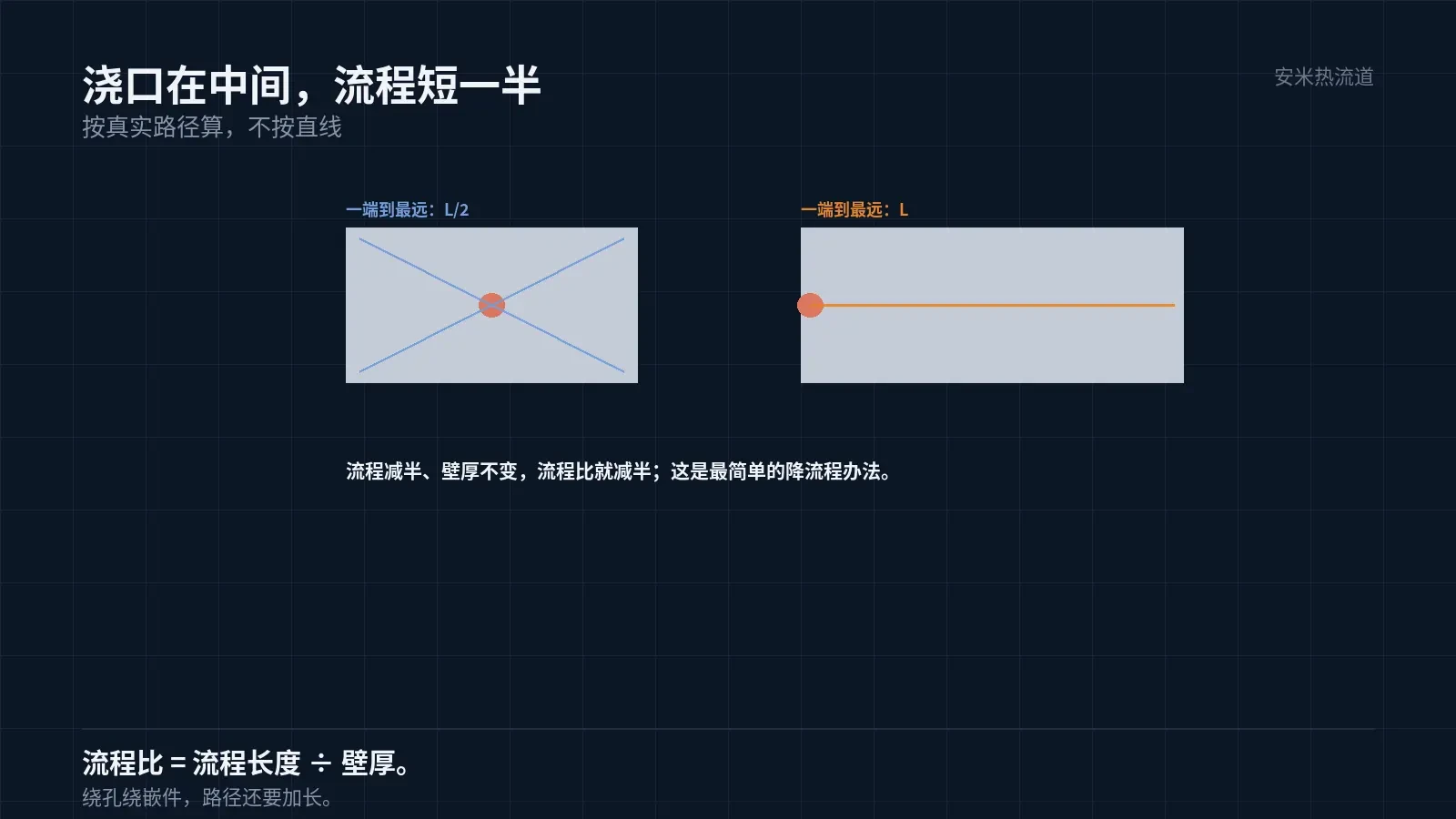
Placing the gate at the part's center minimizes the flow ratio, while placing it at one end maximizes it. For the same part, these two configurations can differ by a factor of two.
If the flow ratio exceeds the material's allowable limit, you may encounter short shots, burns, or weak weld lines. Increasing pressure alone will not resolve this issue.
Thus, the primary criterion for gate location is the flow ratio. If calculations exceed this limit, relocate or add gates.
Allowable flow ratios vary by material and wall thickness. Thin-walled parts have lower limits; thick-walled parts allow higher limits. Highly glass-filled materials have lower limits; unreinforced materials allow higher limits.
Calculate the flow ratio based on the actual path. Paths around holes, inserts, or bosses are longer; calculating using straight lines underestimates the ratio.
Underestimation can result in a "calculated as sufficient but incomplete fill." Therefore, exercise caution during design reviews.
A conservative approach adds a 20% margin to the flow length. A larger margin may require increased wall thickness, but this is more cost-effective than modifying the mold after trial molding.
For parts with long flow lengths, verify the injection molding machine's pressure limit. If the calculated pressure exceeds the machine's capability, the solution is invalid.
Second Constraint: Weld Line Position
Weld lines form where two melt fronts meet. Moving the gate location shifts the weld line accordingly.
In single-gate parts that flow around a hole, the weld line forms directly behind the hole. If this location is in a load-bearing area, part strength will be insufficient.
In multi-gate parts, weld lines form at the midpoints between adjacent gates. Evenly spaced gates produce evenly distributed weld lines.
Therefore, when determining gate locations, first map weld line positions and identify intersecting structures. Weld lines on ribs are acceptable; those on snap-fits are not.
This information is visible directly in mold-flow analysis, eliminating the need to wait for trial molding. It should be reviewed during the design phase.
Third Constraint: Orientation and Warpage
The gate controls melt flow direction, which dictates glass fiber orientation and ultimately determines the warpage direction.
A long-edge gate aligns orientation with the length, causing bowing along that axis. A center gate with symmetric ends results in W-shaped warping.
Controlling warpage requires controlling the gate. Modifying the gate is more effective than adjusting process parameters and more cost-effective than changing materials.
For parts with strict warpage requirements, determine gate location by back-calculating from allowable warpage directions.
This factor is frequently overlooked during design reviews, resulting in costly mold modifications when warpage is detected during trial molding.
Fourth Constraint: Venting
The final position reached by the melt is where air must exit; venting is required at this location.
If the gate is at one end, air flows to the opposite end and requires vent grooves; if the gate is in the center, air flows outward and requires perimeter venting.
Poor venting leads to burn marks, gas traces, and weak weld lines at the end—all three defects caused by a single issue.
Once the gate location is set, define the venting position simultaneously. Issue both drawings together.
Vent depth depends on the material, typically ranging from 0.005 to 0.008 mm. Vents that are too deep cause flash; those that are too shallow are ineffective.

Multi-point gating distribution
The objectives of multi-point gating are threefold: reduce the flow ratio, disperse weld lines, and balance cavity filling.
The distribution principle is "equal flow length." The distance from each gate to the farthest point in its assigned area must be similar. Unequal flow lengths cause some paths to fill before others.
More gates aren't always better. Each additional gate introduces another weld line, an extra runner system, and more scrap.
Empirically, there is an upper limit to the area served by a single gate. Exceeding this limit causes unstable filling. This limit is determined through trials based on part geometry and material.
Gate dimensions may vary in multi-point gating systems. Use larger distal gates and smaller proximal gates to ensure simultaneous arrival across all paths. This technique is called "unequal diameter distribution."
Multi-point injection in hot runner systems
Hot runner multi-gate systems can use valve gates for sequential control. Opening the distant gate first and the near gate later produces a flatter melt front and reduces weld lines.
Sequential control requires independent temperature management and actuation for each gate. Costs are higher than those of constant-temperature hot runners.
Sequential parameters are hard to tune and require mold trials. A 0.1-second difference in valve opening timing alters the flow front shape.
For fast-freezing materials like LCP and PEEK, the sequential control window is narrow. Delaying valve opening may cause the initially opened gate to freeze prematurely.
Therefore, use sequential control for materials with moderate flowability that do not freeze too quickly. For fast-freezing materials, balanced filling is more stable.
Review Checklist
When reviewing a mold gate scheme, verify four items: flow length ratio within limits, weld lines avoiding stress-bearing areas, orientation aligned with warpage requirements, and venting covering the fill end.
If all four checks pass, the scheme is approved. If any one fails, it must be revised; process adjustments cannot compensate.
Remedies include changing the gate location, adding gates, or modifying the part structure. Costs increase in that order.
Please provide the part drawing, wall thickness, material grade, and current gate design. We will review flow balance and weld lines according to our process before confirming pricing.
MATCHED BY MATERIAL AND DEFECT
This article covers stringing, drooling, clogging, and high-heat resins; refer to SD for gate freeze and break-off.
Register for a selection review and quote
Submit part, mold, and material details. Our engineers will evaluate the gate solution per part and provide a quote.
Upload a 2D layout drawing using the form.
Online selection and quote
Scan to register