
PPS Locking Clips in Wire-to-Board Connectors: Brittle Failure Analysis
Material Applications17 min read
On this page
PPS offers practical advantages for online board-to-board connectors: high-temperature resistance, low water absorption, and dimensional stability without deformation during wave soldering. As a result, many connector housings are made from PPS.
However, the failure rate for PPS locking clips is significantly higher. A common issue on assembly lines is "breaks upon bending." This article explains where failures occur, why they happen, and how to improve them.
Fracture locations are nearly fixed.
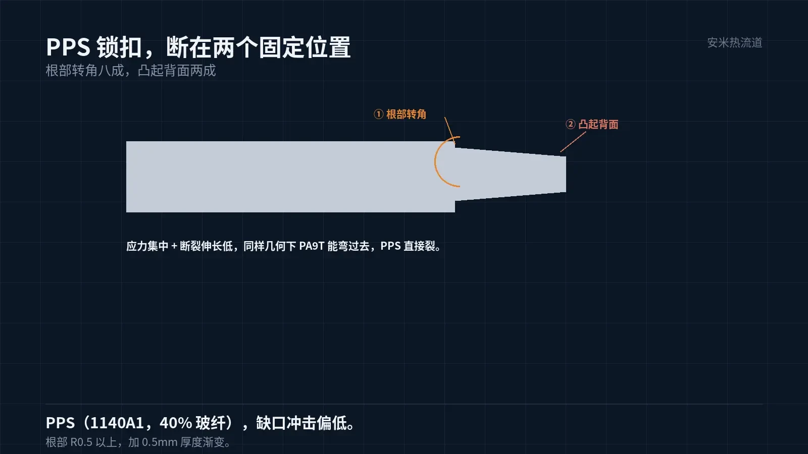
80% of PPS locking clip fractures occur at the root fillet. The remaining 20% occur on the back side of the protrusion. Both locations are stress concentration points.
The root fillet is a geometric discontinuity where a thin wall connects to the main body, with thickness changing abruptly from 0.5 mm to 1.5mm.. If the fillet radius is only R1, the stress concentration factor becomes very high.
PPS with 40% glass fiber exhibits high modulus and low elongation at break. The combination of stress concentration and limited elongation leads to brittle fracture. Under identical geometry, PA9T can flex, whereas PPS cracks directly.
The back side of the protrusion marks the end of melt flow. Glass fibers accumulate here with disordered orientation, resulting in lower strength than the main body. Fractures at this location are typically caused by weld lines or glass fiber agglomeration.
Therefore, "breaking upon bending" is caused not by poor material quality, but by the combination of geometric and flow factors. Improving either factor reduces the failure rate by half.
Geometry Modification: Distribute Stress
First, set the root fillet radius to at least R0.5. Each 0.1mm increase in fillet radius reduces the stress concentration factor by one level with minimal cost (only additional mold polishing).
Second, add a transition section. For thin walls transitioning from 0.5 mm to the main body thickness of 1.5mm,, include a 0.5 mm long gradient to distribute the thickness change along the length.
Third, avoid sharp corners. If the back side of the protrusion has right angles, change them to R0.2 fillets to shift the fracture location away from the back side.
All three are structural changes that must be finalized before mold opening. Modifying the steel after mold opening costs several times more and extends lead time.
After implementing these three changes, the latch's flex life typically doubles or more. This is based on measured comparisons of similar parts before and after modification, not estimates.
After modification, retest insertion and extraction force. Fillets and gradients change latch stiffness, which may cause the force to drop below the lower limit; this must be verified on the first article.
If insertion or extraction force drops, adjust the protrusion height first—not the fillet. Protrusions primarily control force; fillets primarily affect lifespan. Do not mix adjustments.
If the part geometry is customer-defined and cannot be modified, material substitution is the only option. PPS brittleness is an inherent material property that process parameters cannot resolve.
Another often overlooked point: draft angle for the latch. Both sides of the thin wall require a draft; single-sided draft causes thickness variation along the length, leading to failure at the thinner end first.
Provide a draft angle of 0.5–1°, symmetrical on both sides. A small angle can cause surface damage during ejection, while a large angle leads to uneven wall thickness. This is especially critical for thin sections compared to broad surfaces.
Modify Flow: Prevent Glass Fiber Buildup in Thin Sections
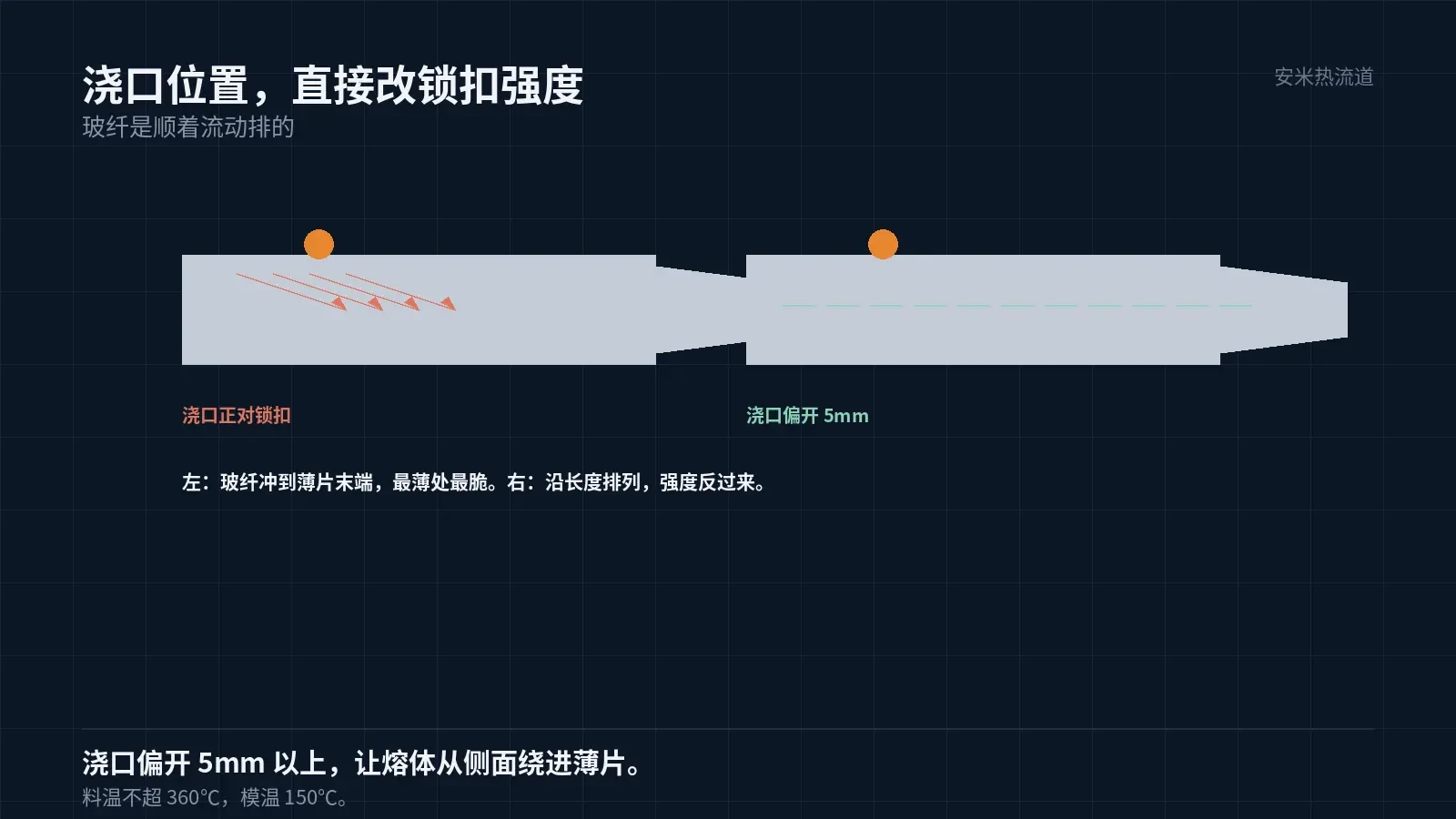
Gate position determines fiber orientation. When the gate faces the latch directly, fibers flow along the melt path to the end of the thin section—the backside of the protrusion, which is the thinnest area and requires maximum strength.
Offsetting the gate so melt enters the thin section from the side aligns fibers along the length, improving strength. This demonstrates the actual impact of gate position on part strength.
Control material temperature. PPS melt temperature must not exceed 360°C; nozzle temperature should be 310–320°C. Excessive temperature causes fiber-resin separation, leading to resin-rich ends and reduced strength. Insufficient temperature increases melt viscosity, causing fiber breakage.
Maintain mold temperature at 150°C. Low mold temperature causes incomplete crystallization, reducing toughness and making the latch more brittle. This parameter is often compromised to shorten cycle time.
Another PPS Trade-off: Insertion and Extraction Feel
PPS has high modulus, offering minimal compliance during insertion and extraction. When terminals are inserted, force concentrates on the terminals, resulting in a stiff feel and reduced elastic travel.
For frequently mated/unmated wire-to-board connectors, high mating force leads to poor user experience and accelerated terminal fatigue.
Mitigation involves increasing the terminal slot clearance to allow movement. Clearance size must be calculated based on the terminal's elastic travel, not estimated by feel.
This conflicts with dimensional tolerances: increasing clearance reduces retention force. Both metrics must be tested together, not individually.
When to Use PPS
PPS is ideal for wire-to-board applications involving wave soldering, proximity to heat sources, or long-term operation above 120°C. Its thermal resistance and dimensional stability make it optimal for this range.
Conversely, if the component primarily undergoes mating/unmating cycles, latches experience repeated flexing, and operating temperatures are low, PA9T or PA46 is more appropriate.
Therefore, material selection for wire-to-board connectors should first determine whether the primary failure mode is thermal aging or mechanical fatigue. The answer dictates the choice of materials.
Validation
Group 1 performs latch flex testing: conduct reciprocating flexing at 1.5 times the customer's specified mating cycles, recording fracture count and location. Group 2 measures insertion/extraction force: compare the force difference between the first and 1,000th cycle.
Group 3 performs reflow and wave soldering tests: remeasure latch dimensions and flex life after processing. PPS excels in this group—post-soldering data remains virtually unchanged.
Please provide the part drawing, latch dimensions, insertion/extraction cycle counts, and welding method. We will review based on stress analysis and gate design, then submit a quote upon confirmation.
MATCHED BY MATERIAL AND DEFECT
This article covers stringing, drooling, clogging, and high-heat resins; refer to SD for gate freeze and break-off.
Register for a selection review and quote
Submit part, mold, and material details. Our engineers will evaluate the gate solution per part and provide a quote.
Upload a 2D layout drawing using the form.
Online selection and quote
Scan to register