
LCP for Wire-to-Board: Why Thick Walls Sink and Thin Walls Short?
Material Applications16 min read
On this page
Wire-to-board connectors differ from board-to-board types: one end is thick, the other thin. The body wall thickness is 1–2 mm, and terminal slots are only 0.3–0.5mm, apart, with a thin locking tab in between.
When molded in LCP, the most common defects appear at both ends: sink marks on the back of the body and short shots at the end of terminal slots. These two opposing issues occur simultaneously within the same part and mold. This article explains their causes.
Thick sections resist packing pressure
LCP melt temperature ranges from 335 to 345°C, while the mold temperature is only 80 to 120°C. Upon entering the cavity, the surface layer solidifies within tens of milliseconds, forming a hard skin.
In the 1.5mm-thick body region, the core stays molten while the surface solidifies. Packing relies on forcing material through the gate to compensate for volumetric shrinkage, but this skin blocks the flow path.
The result is internal shrinkage and surface sinking. Voids form in the mid-to-rear section of thick walls, while surface depressions appear on the back side—the area that typically cools last.
This issue is not caused by insufficient packing pressure. Increasing pressure will not open the skin or allow material to enter. Effective solutions include adjusting the gate location and adding feed channels for thick walls.
Common approaches include adding overflow wells in thick sections or converting solid walls to hollow rib structures. Design changes are more effective than process adjustments but must be finalized before tooling begins.
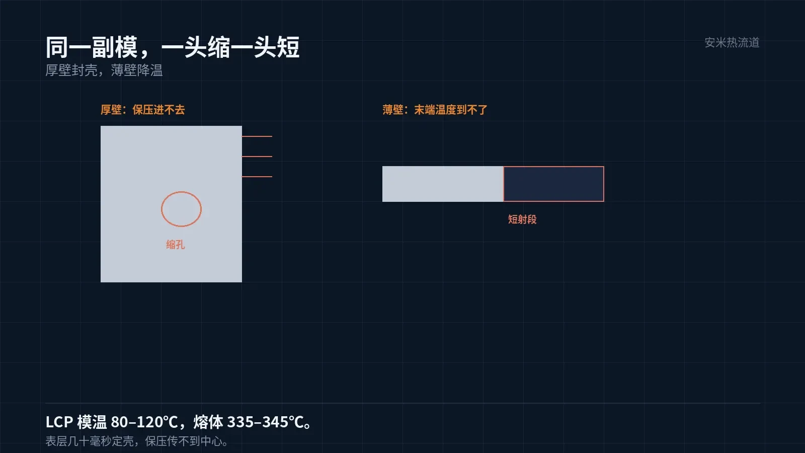
Temperature cannot reach the target in thin sections
Terminal slots are 0.3–{1.5 mm with a high flow length ratio. In such channels, melt pressure drops and cools rapidly; by the time it reaches the end, the temperature has fallen below the minimum flow limit.
LCP's processing window is inherently narrow; a melt temperature drop of just over 10°F prevents filling. Therefore, short shots at thin-wall ends are fundamentally a temperature issue.
Raising the material temperature is the most direct solution, but LCP has an upper limit due to degradation risks. Hot runner temperatures of 335–345°C are already within its typical operating range; increasing them further raises the risk of degradation and black spots.
Another option is to move the gate toward the thin-wall end. However, this extends the flow path into thick sections, increasing sink marks. This remains a key challenge when using LCP for wire-to-board connectors.
Our method addresses these separately: the primary gate prioritizes thin walls (since short shots are unfixable), while thick walls are compensated via overflow wells or secondary packing. Solving these issues independently avoids forcing a single gate to handle both.
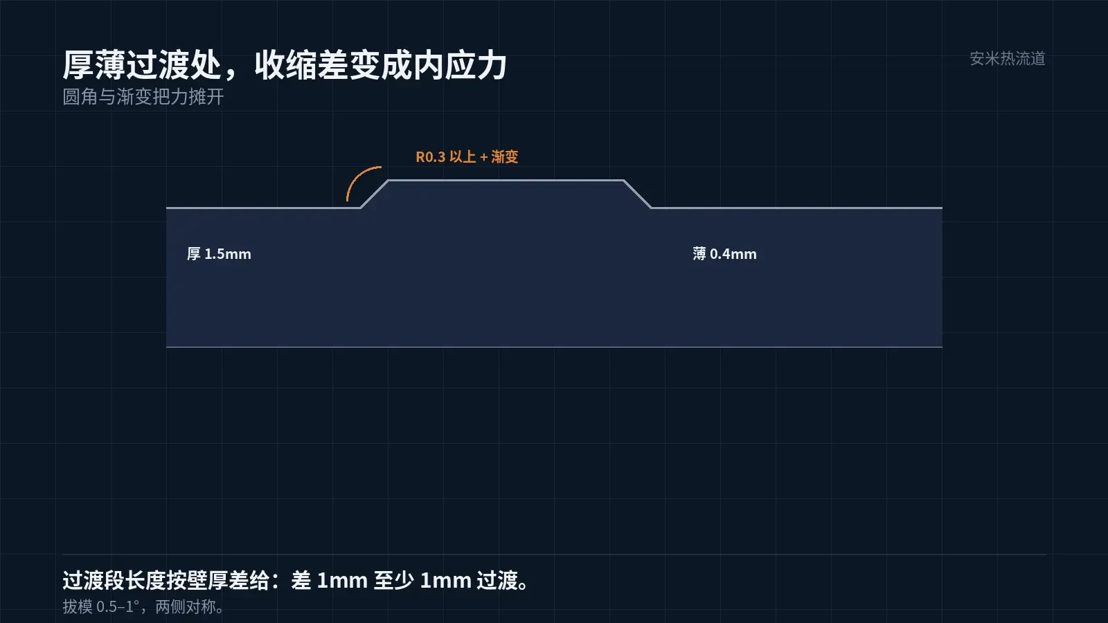
Wall thickness transitions are stress concentration points.
When wall thickness changes abruptly from {0.5mm to 0.4mm,, shrinkage differs several-fold between the two sides. During cooling, the thicker side shrinks more than the thinner side, generating internal stress at the junction.
This internal stress is not visible on the part but appears during assembly: locking clips crack when bent, and terminal slots deform, preventing insertion.
Structural design requires smooth transitions: add fillets with R0.3 or greater, or create a gradual transition section 0.3–{2.5} mm long. The transition zone length depends on the wall thickness difference; a 1 mm difference requires at least a 1 mm transition.
This feature is not visible in mold flow analysis; only experienced users request it for similar parts before tooling.
The transition section location must be carefully selected. Positioning it between the terminal slot and body causes high melt velocity changes, resulting in flow marks; placing it behind the latch conceals these marks due to the structure.
Flow marks in LCP exhibit another characteristic: orientation differences occur both internally and on the surface. On polished parts, surface flow marks are hidden, but local brittleness becomes apparent during assembly.
Gate and Hot Runner
For LCP, SD, VG, and PVG are suitable; TP is not. Wire-to-board cavitation is typically low (2–8 cavities). SD is preferred for its small gate mark and clean break-off.
Gate diameter must be adequate. Due to LCP's low viscosity, small gates induce high shear and melt degradation, causing black spots that typically appear in thin-wall terminal slots and cannot be repaired.
Balancing multi-cavity molds is straightforward: LCP solidifies quickly, minimizing fill time differences between cavities. This is an advantage for wire-to-board applications, especially with high cavity counts and low part weights.
Set the hot runner temperature to 335–345°C across at least two zones: nozzle and manifold. Set the nozzle zone slightly higher to prevent gate freezing.
The temperature controller must display the actual temperature for each zone, not just the setpoint. LCP has a narrow processing window; a deviation of 5°C in actual temperature can cause issues, rendering the setpoint irrelevant.
Verification and Judgment
Group 1: Inspect sink marks by cutting thick sections or measuring back-side depression depth with gauges. Group 2: Verify full fill at terminal slot ends in thin walls using pin gauges. Group 3: Snap latches after assembly to check for fractures at transition areas.
Among the three groups, the third is most easily overlooked. Sink marks and short shots appear on first articles, but internal stress at transitions only becomes apparent during assembly.
If all three issues occur simultaneously, prioritize fixing the thin-wall path. Short shots result in scrap, sink marks are cosmetic defects, and cracks at transitions compromise reliability. Apply corrections in this order.
Reversing the correction order wastes effort. Adjusting holding pressure first to fix sink marks worsens thin-wall short shots; increasing melt temperature first to fix thin walls causes black spots and degradation in thick walls.
Send us the part drawing (including wall thickness distribution), cavity count, terminal slot dimensions, and reflow profile. We will verify gate and packing solutions based on the thick-to-thin ratio and provide pricing upon confirmation.
MATCHED BY MATERIAL AND DEFECT
This article covers stringing, drooling, clogging, and high-heat resins; refer to SD for gate freeze and break-off.
Register for a selection review and quote
Submit part, mold, and material details. Our engineers will evaluate the gate solution per part and provide a quote.
Upload a 2D layout drawing using the form.
Online selection and quote
Scan to register