
Critical Interface Considerations When Installing Hot Runners into Molds
Material Applications16 min read
On this page
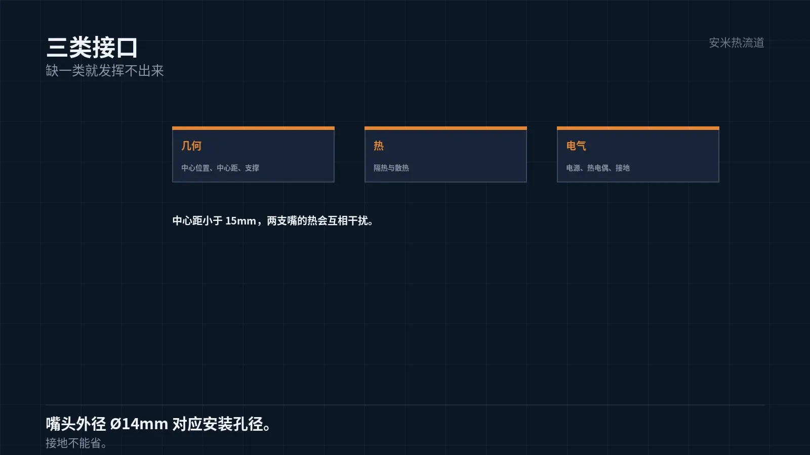
There are three types of interfaces between the hot runner and the mold: geometric, thermal, and electrical. If any one is incorrect, the hot runner will not function.
Interface issues do not occur at factory shipment; they arise during mold installation or mass production.
Geometric Interface: Positioning and Fit
The first positioning factor is the nozzle tip's center location. Misalignment results in off-center gate marks on the part.
Positioning relies on mounting holes in the mold. The hole diameter must match the nozzle tip OD; a Ø14mm nozzle tip requires this specific mounting hole size.
The second factor is the center-to-center distance between adjacent nozzles. Insufficient spacing causes thermal interference, leading to elevated mold temperatures in the intermediate zone.
The minimum center-to-center distance between adjacent nozzles is 15 mm. Smaller distances complicate structural design and heat dissipation.
The third factor is manifold support. The manifold requires a supporting surface and cannot be suspended, as suspension causes deformation under thermal conditions.
Thermal Interface: Insulation and Heat Dissipation
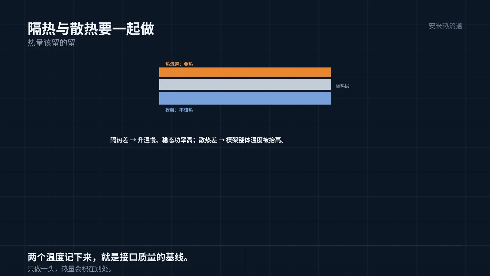
The purpose of insulation is to retain heat where needed and prevent heat transfer to the mold base.
Poor insulation causes slow heating, high energy consumption, and elevated mold temperatures. Higher mold temperatures extend cooling time.
Insulation requires adding insulating pads between the manifold and mold base, with material and thickness determined by temperature requirements.
Heat dissipation maintains low temperatures in areas that must stay cool, such as junction boxes and specific mold base regions.
Insulation and heat dissipation complement each other. Insulation without dissipation causes heat buildup elsewhere; dissipation without insulation leads to excessive heat loss.
Insulation quality is evaluated by heating time and steady-state power. Poorly insulated hot runners show slow heating and high steady-state power.
Dissipation adequacy is also evaluated directly through mold base temperature. A generally elevated mold base indicates heat leakage from the hot runner and insufficient dissipation.
Both assessments rely on temperature readings instead of disassembly. Record these temperatures during commissioning to establish a baseline for interface quality.
The baseline's value lies in comparability. When replacing a hot runner in the same mold, comparing these two temperatures immediately reveals interface performance.
Therefore, these two aspects must be designed together and cannot be addressed in isolation. This is the most commonly oversimplified part of interface design.
Electrical Interface: Wiring and Protection
Wiring covers heater power, thermocouple signals, and grounding. All three circuits must be reliable.
Reliability means secure connections with no looseness or miswiring. Miswiring can burn out heaters, while looseness causes temperature fluctuations.
Connectors must be clearly identified. Pinouts vary by manufacturer; unlabeled connectors lead to wiring errors during staff turnover.
Grounding is required. If the insulation between the heater and mold base fails, lack of grounding creates a safety hazard.
The junction box location must be carefully planned. Placing it too close to hot zones accelerates cable aging, while placing it too far complicates routing.
Assembly Sequence
Assembly sequence: install the manifold and nozzles first, followed by insulation and supports, and finally wiring.
Wiring is performed last to prevent cable damage during assembly. Cables are the most fragile components.
After assembly, perform cold-state verification: check position, fit, wiring, and insulation. All four checks must pass.
Then perform hot-state verification: check for material leakage, abnormal temperature rise, and temperature uniformity.
Proceed to mold trial only after both verifications pass. Skipping cold-state verification and heating directly makes fault localization difficult.
A frequently overlooked step in cold-state verification is nozzle rotation. Slight rotational freedom indicates whether the nozzle is jammed or over-constrained.
An over-constrained nozzle cannot accommodate thermal expansion when hot, forcing displacement toward the gate and causing misalignment. Therefore, maintain "movable clearance" in the cold state; tighter is not always better.
This clearance conflicts with reliable contact. The solution is to apply preload using springs or floating structures instead of rigid compression during assembly.
The core of interface design is "preloading in cold state, freeing space in hot state." Though seemingly contradictory, this is achieved through structural design that defines the value of mechanical components.
Interface Issue Symptoms
Incorrect geometry causes gate misalignment, part weight variation, and nozzle tip offset.
Improper thermal interface leads to slow heating, high energy consumption, elevated mold temperature, and extended cooling time.
Electrical issues cause temperature fluctuations, single-zone heating failures, and thermocouple reading jumps.
These three symptoms differ but all point to the interface. Troubleshoot the interface first, then the hot runner itself.
Interface troubleshooting sequence is fixed: check cold geometry, verify thermal performance during heating, and inspect electrical systems when powered on.
Following this order, most interface issues can be identified within 30 minutes. Conversely, checking the hot runner first often leads to incorrectly blaming the product for interface problems.
This is especially critical in after-sales service: many complaints about "poor hot runner performance" ultimately stem from mold mounting holes being misaligned by fractions of a millimeter.
Deviations of less than a millimeter are imperceptible in the static state and appear acceptable when the mold is clamped, but cause gate misalignment after heating.
Therefore, interface dimension inspection must use the "same datum as assembly." Independent measurements yield correct values, but misalignment persists during assembly.
Please provide the mold's mounting hole dimensions, center distances, insulation method, and wiring definitions. We will verify these against the interface specifications before providing a quote.
MATCHED BY MATERIAL AND DEFECT
This article covers surface gating or small precision parts; check TP for gate position and whether a dot mark is acceptable.
Register for a selection review and quote
Submit part, mold, and material details. Our engineers will evaluate the gate solution per part and provide a quote.
Upload a 2D layout drawing using the form.
Online selection and quote
Scan to register