
Hot Runner Temperature Controllers: Key Capabilities to Evaluate
Material Applications17 min read
On this page
Temperature controllers are often treated as accessories, selected based on "channel count" and price. It's only after selection that the root cause of the issues is revealed to be the temperature controller itself.
Selection should be based on three capabilities, not just channel count.
First Capability: Channel Count and Zones
Channel count is critical. The number of hot nozzles and zones determines the required channel count.
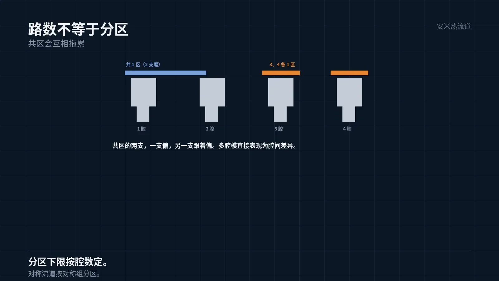
However, channel count does not equal zone count. Controlling one nozzle per zone versus two nozzles sharing a zone produces entirely different control results.
For two nozzles in a shared zone, a temperature deviation in one causes the other to follow. In multi-cavity molds, this manifests as inter-cavity variation.
Therefore, when selecting a temperature controller, first determine the "required number of independent zones," then the "required number of channels." These two values may differ.
Finer zoning increases cost but ensures consistent, controllable results. Coarser zoning reduces cost but makes process tuning dependent on luck. This is the first trade-off.
The minimum zoning standard is "per cavity." A four-cavity mold requires at least four zones, and an eight-cavity mold requires eight zones to enable independent compensation for each cavity.
Zoning must also account for "symmetry." For geometrically symmetric runners, corresponding cavity temperatures affect each other; therefore, zoning should follow the symmetry pattern.
Asymmetric flow channels create inherently uneven loads across circuits, requiring finer zoning. This is a key aspect of manifold design.
Excessive zoning incurs costs: each zone requires a thermocouple and power channel, increasing failure points and wiring complexity.
Therefore, the zoning principle is "sufficiency." The sufficiency standard requires that each cavity be independently adjustable without affecting others.
Second Capability: Accuracy and Response
Accuracy indicates how precisely the setpoint is maintained; response indicates how quickly deviations return to the setpoint. Both must be evaluated.
In temperature controllers with low accuracy, discrepancies of several degrees between readings and actual values can affect parts. This error is negligible for small parts but becomes significant for large and precision components.
Slow-response temperature controllers cannot keep up with rapid temperature changes. FHFC requires second-level response; slow response effectively eliminates variable temperature control.
To evaluate response, analyze the heating curve: time from room temperature to setpoint and overshoot magnitude. These metrics are more practical than datasheet parameters.
Also consider cooling. While heating is straightforward, cooling depends on heat dissipation; many temperature controllers lack sufficient cooling capacity.
A variable-temperature system's cooling capacity often determines its viability. This factor is frequently overlooked during selection.
Another factor affecting cooling is mold heat dissipation. Temperature controllers manage heating only; cooling relies on the mold's water channels.
Therefore, evaluate cooling with the mold included. Relying solely on temperature controller parameters leads to overly optimistic results.
Actual test method: Install the mold, heat to operating temperature, cut off heating, and record the time to cool from operating temperature to target temperature. This reflects true response.
This duration must align with the molding cycle. If cooling is insufficient, the controller-mold system cannot meet variable temperature requirements.
Therefore, whether a temperature controller can handle variable temperatures depends not on the unit alone, but on the "unit + mold" combination.
During selection, require suppliers to validate jointly using actual molds, actual materials, and actual curves.
Joint validation is costly but cheaper than production issues. It's standard practice for rapid thermal cycling projects.
After successful validation, document curves and parameters in process specifications. Execute production based on documentation, not memory.
Third Capability: Protection and Logging
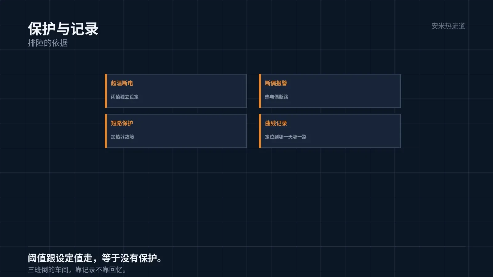
Protection features: over-temperature power cutoff, thermocouple open-circuit alarm, and heater short-circuit protection. All three are required.
The over-temperature cutoff threshold must be set independently of the setpoint. If adjusting the setpoint also changes the protection limit, no effective protection is provided.
Logging includes temperature curves, alarm history, and parameter change records. These records serve as the basis for troubleshooting.
This feature is critical for mass production. When issues arise, analyzing the curves helps identify the exact day, channel, and time.
Without logs, you rely solely on memory. Memory is unreliable, especially in three-shift workshops.
Matching with Hot Runner
Ensure the temperature controller matches the nozzle tip's power rating. Using a low-power controller with a high-power nozzle tip will cause slow heating and prevent the system from reaching the setpoint.
It must also match the thermocouple type. K-type and J-type use different calibration codes; mixing them results in inaccurate readings.
It must also match the connector. Pin definitions vary by manufacturer; incorrect wiring can damage the heater.
All three factors operate at the interface level. If interfaces don't match, functionality doesn't matter.
Therefore, when selecting components, provide the supplier with the nozzle tip model, power rating, thermocouple type, and connector pinout.
On-site Acceptance
The first acceptance step is "no-load heating": power on without the mold installed to verify the heating curve and overshoot.
The second step is "loaded heating": install the mold to verify setpoints and assess temperature differences between zones.
Step 3: Power Failure Recovery – Simulate a power outage to verify post-recovery temperatures and alarm logs.
Acceptance passes only when all three steps succeed. No-load testing alone does not reflect actual operating conditions.
Another step is "continuous operation": run the system in production for several hours to check for temperature drift. Drift indicates heat dissipation or control issues.
Please provide the number of circuits, zones, hot nozzle power, thermocouple type, and connector definitions. We will verify these against the system and issue a quote upon confirmation.
MATCHED BY MATERIAL AND DEFECT
This article covers surface gating or small precision parts; check TP for gate position and whether a dot mark is acceptable.
Register for a selection review and quote
Submit part, mold, and material details. Our engineers will evaluate the gate solution per part and provide a quote.
Upload a 2D layout drawing using the form.
Online selection and quote
Scan to register