
Thermocouple Placement: What Temperature Are You Actually Controlling?
Material Applications16 min read
On this page
The temperature shown on the controller is measured at the thermocouple location and may not reflect the actual melt temperature.
The difference depends on thermocouple placement. Incorrect positioning renders adjustments ineffective.
Three Locations, Three Temperatures
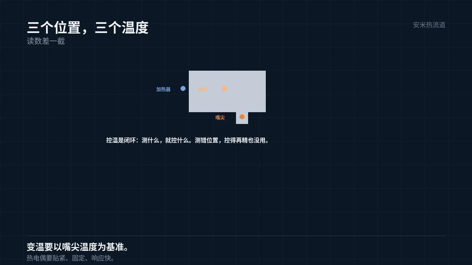
Mounted on the heater band, it measures the heater temperature. This value differs from the melt temperature by an amount determined by the heat transfer path.
Mounted on the nozzle body, it measures body temperature. This reading is closer to the melt than the heater but still does not reflect the actual melt temperature.
Mounted near the nozzle tip, it approximates the actual gate temperature. This is the most meaningful yet challenging location for installation.
Readings vary across these three locations. To set the temperature, first select a measurement point.
This detail is often missed during handovers: using original settings with a different controller leads to incorrect temperatures.
Why Sensor Placement Matters
Temperature control is a closed loop: it regulates what it measures. If the sensor does not measure the melt, the system cannot control it.
Controlling heater temperature stabilizes the heater, but melt temperature may still fluctuate due to flow rate, shear heating, and cycle time.
Controlling the nozzle tip temperature stabilizes the tip and, consequently, the melt, since the nozzle tip is the final point before the melt enters the mold cavity.
Therefore, control accuracy depends on sensor placement. Incorrect sensor positioning renders precise control ineffective.
This is especially critical in rapid thermal cycling systems, where the magnitude and speed of temperature variation must be referenced to the nozzle tip temperature.
Sensor Mounting and Response Speed
Thermocouple response times depend on sheath diameter and mounting tightness.
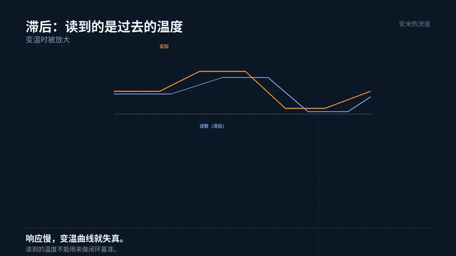
Slow-response thermocouples report historical temperatures; this lag is amplified during thermal cycling.
For thermal cycling systems, use tightly mounted fast-response thermocouples. Loose sensors cause unstable readings.
Tight contact also requires fixed positioning. Vibration during production can displace the thermocouple, causing reading fluctuations.
On-site, this manifests as intermittent temperature instability. Wiring and controller checks are normal; the root cause is a loose thermocouple.
Another sign of looseness is temperature variation across shifts, even with identical setpoints. Shift handovers that alter machine states can affect readings.
Therefore, thermocouple fixation must withstand vibration. Spring-loaded compression or ferrule locking is more reliable than simple insertion.
A hidden issue is the bimetallic effect. Poor cold-junction compensation in thermocouples causes systematic reading errors.
Systematic deviation occurs when all points shift in the same direction. Individual point deviations indicate positional issues; global deviations signal compensation problems.
Compensation issues do not necessarily require controller repair. First, perform temperature offset calibration to quantify and uniformly correct deviations.
Calibration requires stable deviations. If the deviations fluctuate, the resulting correction values become unreliable.
Temperature Control Accuracy
Temperature control accuracy depends not only on the controller but also on measurement precision, heating power regulation capability, and system thermal inertia.
Systems with high thermal inertia cannot achieve precise control. Large heater mass causes slow heating and cooling rates, forcing the controller to act too early or too late.
Accurate control requires minimizing thermal inertia, which depends on both the heating method and structural design.
Another factor affecting accuracy is zoning. Multi-zone independent temperature control reduces per-zone thermal inertia for better precision, while single-zone global control is inherently coarse.
The number of zones must align with the cavity count and part requirements. Higher cavity counts and stricter requirements demand finer zoning.
Overshoot and Protection
Overshoot is a common issue in temperature control. After heating stops, residual heat causes the temperature to continue rising for a period.
Overshoot magnitude depends on thermal inertia and the control algorithm. High inertia with simple algorithms causes significant overshoot.
Overshoot is dangerous for high-temperature materials. PA46 degrades above 320°C, so a 10°C overshoot can cause issues; the maximum melt temperature for PPS is 360°C.
High-temperature applications require independent over-temperature protection, not just reliance on controller setpoints.
Protective action must be "cut heating," not "reduce power." Reducing power still generates heat, just more slowly; overshoot persists.
On-site verification methods
Step 1: Comparison — Use an external thermometer to measure the actual nozzle tip temperature and compare it with the controller display.
Comparisons must be performed under stable production conditions, not during idle operation. Idle running lacks shear heating, leading to lower temperatures.
Step 2: Relocation Re-measurement. Move the thermocouple to a different position and observe changes in the reading. Significant changes indicate the original position was inaccurate.
The third step is "recording": document the relationship between position, reading, and part quality to generate a temperature profile for this mold.
Profiles, personnel changes, box swaps, or seasonal shifts let you quickly restore correct settings. This is more reliable than relying on experience alone.
Profiles must specify "material + color + number of cavities." Settings vary significantly depending on the material molded in the same mold.
Profiles must also specify "which hot nozzle, which zone." Correct settings may vary by location within the same mold.
This record is only truly usable at this level of granularity. Stating simply "this mold runs at 300°C" becomes invalid when the cavity position changes.
Please provide the material, heating method, current temperature measurement locations, and temperature fluctuation data. We will verify compliance with temperature control and structural requirements before providing a quote.
MATCHED BY MATERIAL AND DEFECT
This article covers stringing, drooling, clogging, and high-heat resins; refer to SD for gate freeze and break-off.
Register for a selection review and quote
Submit part, mold, and material details. Our engineers will evaluate the gate solution per part and provide a quote.
Upload a 2D layout drawing using the form.
Online selection and quote
Scan to register