
Manifold Temperature Inconsistency Leading to Part Defects
Material Applications17 min read
On this page
In a multi-cavity hot runner system, the manifold distributes melt to each nozzle tip, balancing both flow rate and temperature.
Uneven temperature distribution causes inconsistent part dimensions and appearance. This is one of the most challenging issues in multi-cavity molds.
Manifold Function
The manifold is a plate with flow channels. Melt enters through the inlet, splits into multiple paths along the channels, and feeds into individual nozzle tips.
Its two primary tasks are balancing flow rate and balancing temperature. The former relies on channel geometry; the latter depends on heating and insulation.
These tasks are interdependent. Longer flow paths increase pressure drop and reduce flow rate; compensating for flow often requires enlarging the channel, which in turn affects temperature.
Therefore, manifold design requires simultaneous calculation of flow and temperature, not sequential flow-first then temperature adjustment.
The standard approach determines channel diameter based on flow requirements, uses heated zones to equalize temperature, and calibrates with actual measurements. All three steps are essential.
Calibration is often skipped. Jumping straight from drawings to mold fabrication can reveal significant cavity-to-cavity variations, where modification costs far exceed those of proper calculation.
Calibration does not necessarily require a physical mold. Flow simulation software can identify paths with excessive pressure drop or low temperatures, enabling design adjustments before mold fabrication.
This is especially true for 8-cavity and 16-cavity molds. More cavities increase path length differences, making consistency harder to achieve.
Sources of Temperature Inconsistency
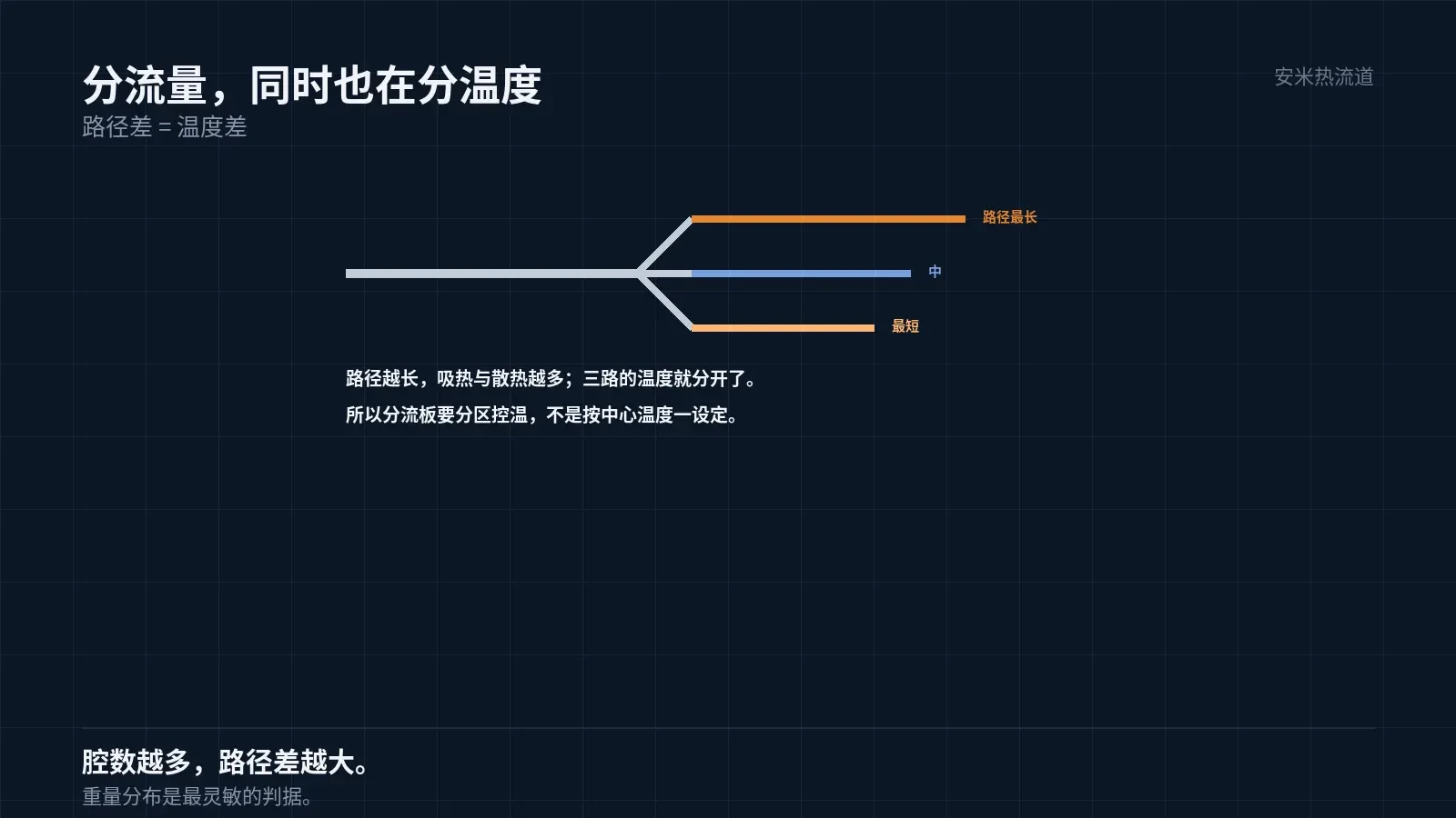
The first source is path length difference. Melt residence time varies within the runner, causing differences in heat absorption and dissipation.
The second source is the heater arrangement. The position of heating bands or rods determines where heat enters and how it flows.
The third source is heat loss. Heat exchange occurs between the manifold and the mold base or surrounding environment, with edge paths dissipating heat more rapidly.
These three factors create a non-uniform temperature distribution across the manifold, with some areas hotter and others cooler.
This distribution is neither uniform nor symmetrical. As a result, setting based on center temperature often fails to ensure identical conditions across all cavities.
Why This Causes Part Defects
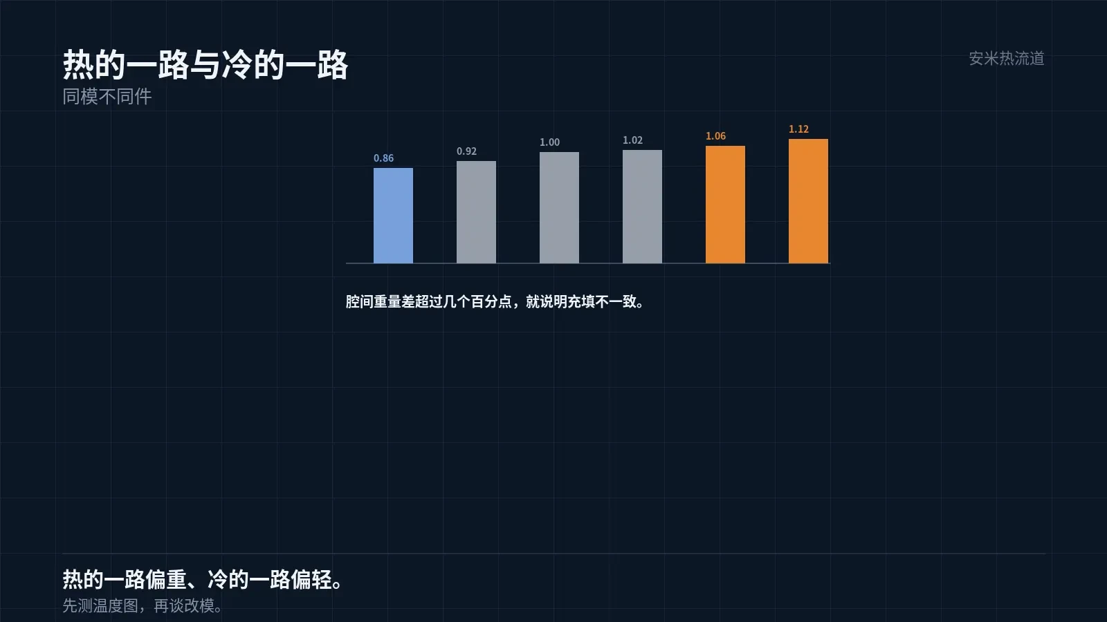
In the hotter channel, lower melt viscosity leads to faster filling and improved packing pressure transfer, resulting in parts with larger dimensions and greater weight.
In the cooler channel, melt viscosity increases, filling slows down, and packing pressure transfer becomes ineffective, leading to smaller part dimensions or even short shots.
Therefore, temperature inconsistency directly causes "parts from the same mold to vary." This is common in multi-cavity molds.
Indirect indicators include flash on the hot side, sink marks on the cold side, color variation, and gate mark size differences.
On-site, these are often attributed to "mold issues" or "material issues," but they actually stem from temperature distribution problems.
Diagnostic method: Measure the temperature of each cavity. If uneven, it's a temperature issue; if uniform, check the mold and material.
This step saves significant troubleshooting time. For problematic areas in multi-cavity molds, measuring the temperature map first usually identifies the root cause immediately.
Measuring the temperature map is low-cost but requires specific conditions: stable production, same material batch, and at least 30 minutes of continuous operation.
Order of measurement matters: measure each nozzle tip first, then several positions on the manifold. Mixing temperatures from these two levels will lead to inaccurate readings.
How to maintain consistent temperature
Use zoned heating. Divide the manifold into zones with independent temperature control to achieve a uniform temperature distribution.
Zoning requires identifying high and low temperature zones. This relies on measurement, not guesswork. Place sensors near actual airflow paths.
Another approach is thermal isolation. Install insulation between the manifold and mold base to minimize heat loss and enhance uniformity.
Excessive insulation causes problems: inadequate heat dissipation slows heating and cooling, reducing cleaning efficiency during color or material changes. Ensure controlled heat dissipation paths are maintained.
A third method is geometric compensation of flow channels. Narrow short-path channels and widen long-path channels to balance flow via pressure drop.
Verification methods
The most direct way to verify temperature consistency is to run a temperature map: measure actual nozzle tip temperatures under stable production conditions.
Measure at consistent locations near the nozzle tips. Measuring on heaters displays heater temperature, not melt temperature.
Step 2 is "shot testing": collect parts from each cavity within the same shot, measure their weight and critical dimensions, and analyze the distribution.
Weight distribution is the most sensitive indicator. A weight difference exceeding a certain threshold indicates inconsistent filling caused by temperature or runner issues.
Step 3 is "re-testing under changed conditions": run one test after stop/start cycles and material batch changes. For a stable solution, the results across all three tests should be consistent.
Integration with Variable-Temperature Systems
For FHFC nozzles, nozzle tip temperature varies while the manifold must remain constant. The control objectives for these two zones differ.
Therefore, the system must independently control "manifold constant temperature" and "nozzle tip variable temperature." Combining them into a single loop leads to poor control of both.
Manifold temperature stability directly impacts variable-temperature performance. Significant fluctuations cause unstable starting temperatures at the nozzle tips, resulting in temperature profile drift.
This is especially critical for multi-cavity molds: even slight nozzle drift accumulates across cavities, amplifying part-to-part variation.
Provide the number of cavities, runner layout, current temperature control method, and part consistency requirements. We will review the structure and provide a quote upon confirmation.
MATCHED BY MATERIAL AND DEFECT
This article covers surface gating or small precision parts; check TP for gate position and whether a dot mark is acceptable.
Register for a selection review and quote
Submit part, mold, and material details. Our engineers will evaluate the gate solution per part and provide a quote.
Upload a 2D layout drawing using the form.
Online selection and quote
Scan to register