
Where Do Hot Runner Leaks Typically Occur?
Material Applications17 min read
On this page
Drooling is one of the most problematic hot runner failures. It doesn't appear on the part surface; by the time it's detected, mold cavities are already contaminated.
Drooling is limited to a few interfaces. Identifying these locations helps guide troubleshooting.
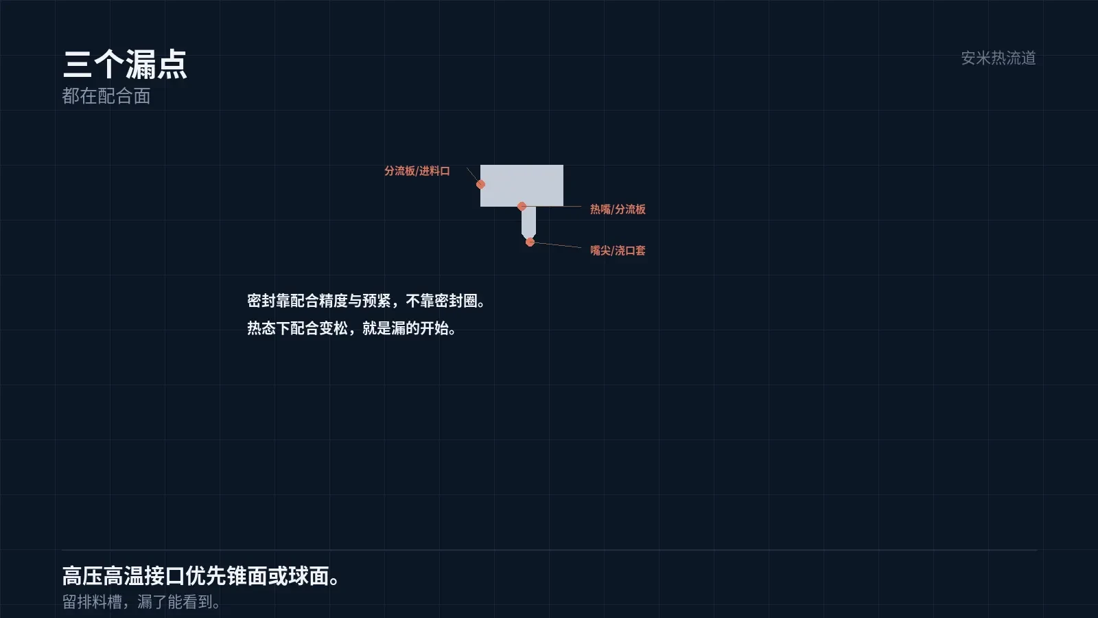
Three Common Drool Points
The first is the contact interface between the nozzle tip and the gate insert. This is the final stage before melt enters the cavity, where pressure is highest and drooling is most likely.
The second is the connection between the hot nozzle and the manifold. Melt flows from the manifold into the hot nozzle; sealing at this interface depends on fit precision and preload.
The third is the connection between the manifold and the inlet. Leakage here causes material to seep outward along the manifold.
All three points share a common feature: mating surfaces between two components. Sealing relies on fit precision and preload force, not O-rings.
Therefore, drooling occurs when the gap at the mating surface under thermal conditions exceeds the melt's tolerance.
Why Leakage Occurs in the Hot State
Clearance is tight in the cold state. In the hot state, varying thermal expansion among components alters the fit. Differential expansion is the primary cause of leakage.
The second cause is preload loss. Spring relaxation and bolt loosening reduce the preload, leading to insufficient contact pressure.
The third cause is wear. Repeated assembly/disassembly and thermal cycling create gaps on mating surfaces; leakage occurs once these gaps accumulate sufficiently.
The fourth cause is deformation. The manifold plate warps at high temperatures, resulting in loss of flatness at the interface.
Among these four causes, differential expansion and preload decay are the most common. Both are heat-related and cannot be detected when cold.
Leakage Consequences
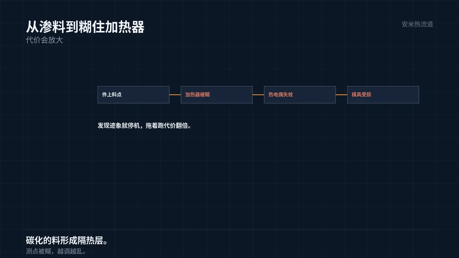
Minor defects include gate marks or resin spots on parts caused by melt seeping through gaps and landing on the surface.
Moderate consequences include heater fouling. Resin seeps onto heaters, carbonizes into an insulating layer, reducing heating efficiency and preventing temperature rise.
Severe consequences include thermocouple failure. Resin can coat the measurement point, causing the controller to read incorrect temperatures and resulting in unstable control.
The most severe consequence is mold damage. Molten material leaks into gaps in the mold base, pushing components apart during cooling or cracking the plates.
Melt leakage must not be ignored. Stop and inspect immediately upon detection; continuing operation will increase costs.
Inspect parts first, then the hot runner nozzle exterior, and finally disassemble. Record temperature and position before disassembly, as this data will be lost afterward.
During disassembly, inspect contact marks to verify preload uniformity or detect misalignment.
Contact marks can also be used for historical comparison. Differences from previous inspections on the same mold indicate a change in condition.
Mark distribution helps distinguish between misalignment and insufficient preload: a uniform shallow ring indicates insufficient preload, while asymmetrical marks indicate misalignment.
Insufficient preload may also result from incorrect bolt tightening sequence. Cross-diagonal tightening ensures uniform force, while sequential clockwise tightening can cause the final bolt to be over-tightened.
Tightening sequence also causes residual stress. The last bolt tightened is the first to loosen under prolonged high temperatures, which can lead to leakage.
Therefore, verify bolt preload during maintenance with a torque wrench. Manual feel cannot detect differences of a few Newton-meters.
Leak-proof design
Structurally, mating surfaces should use "preloaded conical or spherical interfaces." These self-adapting surfaces under preload offer high tolerance for differential expansion.
Flat mating surfaces have tight tolerances. They require high machining precision and significant preload; even minor deviations can cause leaks.
Therefore, conical interfaces are preferred for high-pressure and high-temperature connections. This is standard practice for high-temperature applications such as PEEK.
Another key design feature is "providing a path for leaked material." Include drain grooves or inspection holes to ensure leaks are visible and do not accumulate in the mold.
Thermal isolation is also critical. Separate high-temperature zones from low-temperature zones to minimize misalignment caused by differential expansion.
On-site diagnosis
When material spots appear on parts, check their location first. Spots near the gate may indicate nozzle tip or gate insert issues; spots at the far end of the part may suggest manifold interface problems.
Next, check the distribution across cavities. If all cavities are affected, the issue is with the manifold or inlet; if only specific cavities are affected, it indicates a problem with that particular hot nozzle.
Next, check the temperature. Is the leaking channel's temperature too low? Low temperatures indicate poor melt flow and high pressure at that location, increasing the likelihood of leakage through gaps.
Finally, review the history. How many times has this mold been assembled or disassembled? Have the springs been replaced? Are there signs of wear on the mating surfaces?
Analyzing all four factors together usually ensures an accurate diagnosis. Relying on just one factor often leads to misdiagnosis as a "material issue."
Another factor is whether leakage occurs after material changes. If leakage begins with a new batch, it may be due to altered flowability or increased pressure forcing gaps open.
Prevention and Maintenance
Prevention hinges on "hot-state inspection." Inspect mating surfaces after each mold installation once heated; cold-state inspection alone is insufficient.
Inspection methods include measuring clearance and checking contact patterns. Uniform contact patterns indicate proper preload; patterns skewed to one side indicate misalignment.
Maintenance intervals should be based on the number of heat cycles, not calendar time. Frequent heating and cooling can loosen mating surfaces.
Springs, sealing surfaces, and bolts must be included in the maintenance checklist. These three are the primary defenses against leakage.
Please provide the leak location, shot count, material, and assembly/disassembly history. We will verify the structure and issue a quote upon confirmation.
MATCHED BY MATERIAL AND DEFECT
This article covers stringing, drooling, clogging, and high-heat resins; refer to SD for gate freeze and break-off.
Register for a selection review and quote
Submit part, mold, and material details. Our engineers will evaluate the gate solution per part and provide a quote.
Upload a 2D layout drawing using the form.
Online selection and quote
Scan to register