
Hot Runner Heating Methods: Types and Suitable Applications
Material Applications17 min read
On this page
Heating seems straightforward: power on, heat up. However, the three heating methods differ significantly in terms of heat generation location, uniformity, and response speed.
Choosing the wrong heating method makes subsequent temperature control difficult.
Three Common Methods
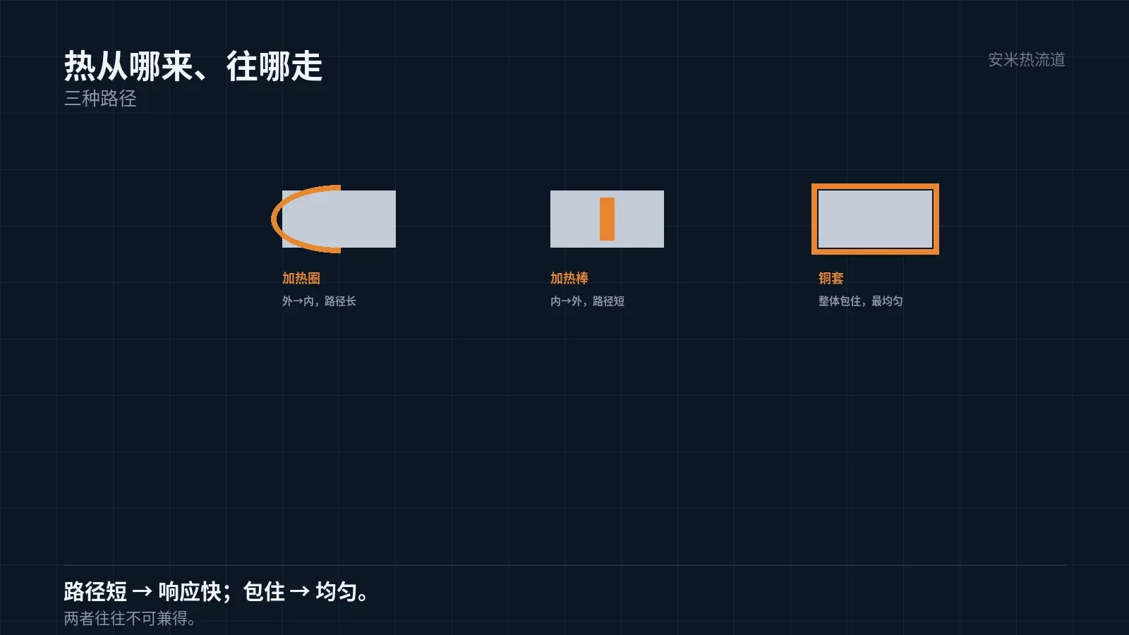
The first option is a heater band wrapped around the nozzle exterior. It features a simple structure and low cost, transferring heat from the outside in.
The second type is a heater rod inserted into the nozzle or manifold. Heat transfers from the inside outward, delivering high thermal efficiency.
The third method uses a copper sleeve or cast copper heating, where the heating element and nozzle are fully enclosed in copper. This ensures excellent thermal conductivity and uniform temperature distribution.
The key difference lies in the "distance from heat source to melt" and the "heat conduction path." A shorter distance and path enable faster response.
As a result, performance varies in terms of "uniformity" and "response speed," resulting in different use cases.
Heater Band Trade-offs
Heater bands heat from the outside in, requiring heat to pass through the nozzle tip's outer wall before reaching the flow channel. This creates a longer path and slower response time.
Circumferential uniformity depends on heater band winding quality and fit. Poor contact causes one side to run cooler.
Its advantages are replaceability and serviceability. If a heater band fails, it can be removed and replaced without disturbing the hot runner body.
Therefore, heater bands are ideal for general-purpose applications where cost and ease of maintenance are priorities. However, their slow response time makes them unsuitable for FHFC.
This is critical: temperature variation must not rely on slow external heating from heater bands.
Heater band power density is also limited. For fast heating, insufficient power requires higher set temperatures, leading to localized overheating.
Insufficient power causes a slowly rising temperature curve even at high setpoints, indicating a power issue rather than a temperature control problem.
Another cause of insufficient power is excessive heat loss. Poor insulation dissipates heating energy, mimicking low-power performance.
Therefore, using heater bands for temperature variation typically leads to slow heating and even slower cooling, failing to meet FHFC requirements.
Heater Rod Trade-offs
Heater rods are inserted internally to transfer heat directly to the hot runner nozzle body. This provides a shorter path, higher efficiency, and faster response compared to heater bands.
However, heater rods have high power density, which can lead to local overheating. Uneven power distribution creates temperature gradients along the rod's length.
Therefore, heater rod design depends on the "number of segments and arrangement." A segmented layout is required to minimize longitudinal temperature differences.
Heater rods are also prone to dry firing. A loose fit against the bore wall impedes heat transfer, leading to excessive rod temperatures and a shortened lifespan.
Therefore, heater rod bore diameter, tolerances, and assembly methods are critical. Poor execution here primarily impacts lifespan.
Heater rod power must match the hot runner's thermal loss. Excessive power causes control oscillation; insufficient power prevents reaching the setpoint.
Oscillation appears as periodic temperature fluctuations around the setpoint. The oscillation period, influenced by thermal inertia, helps diagnose the specific issue.
Replacing heater rods is more complex than replacing heater bands. Disassembly involves handling the hot runner, which increases wear and misalignment risks with each intervention.
Therefore, maintainability must be addressed during the design phase for heater rod solutions, not after failure occurs.
Copper Sleeve Trade-offs
Copper sleeves enclose the heating element and hot nozzle tip in a single copper body, delivering high thermal conductivity and the most uniform temperature distribution.
Uniformity brings consistent results. In multi-cavity molds, cavity-to-cavity variation is typically lower with copper sleeves than with heater bands.
The cost stems from structural complexity and expenses. Copper sleeves require a precise fit with the hot nozzle tip, necessitating high machining and assembly precision, and they are less convenient to maintain than heater bands.
Another advantage of copper sleeves is controllable thermal inertia. Due to copper's high thermal conductivity, both heating and cooling occur quickly, making it ideal for applications requiring variable temperatures.
However, copper sleeves are heavy. Achieving rapid response requires thinning the structure and placing components in close proximity.

Selection Criteria
First, determine if variable temperature control is required. If so, exclude heater bands; copper sleeves and close-proximity heating rods are candidates.
Second, consider part consistency. For multi-cavity or precision parts, prioritize uniformity; for single-cavity parts where appearance is less critical, prioritize cost.
Third, evaluate maintenance conditions. If on-site precision assembly capabilities are lacking, select a solution with high replaceability.
Fourth, evaluate the material. High-temperature materials (PEEK, PPS) are sensitive to temperature uniformity; poor uniformity can amplify defects.
Considering all four factors narrows the selection. Focusing only on cost often leads to choosing "cheap but ineffective" solutions.
Coordinate with Temperature Control
The heating method determines the control target: band heaters regulate outer wall temperature, cartridge heaters control heater body temperature, and copper sleeves manage copper body temperature.
All three values differ from the melt temperature, with the difference magnitude depending on the heat transfer path. Therefore, sensor locations must be defined based on the heating method.
This site-specific issue is often overlooked: switching the heating method while keeping original sensor locations can lead to inaccurate temperature readings.
In reality, this is not a control failure but a shift in measurement location. Sensor positions must be adjusted along with the heating method.
Provide details on material, cavity count, variable temperature requirements, and maintenance conditions. We will verify the heating method and structure before providing a quote.
MATCHED BY MATERIAL AND DEFECT
This article covers stringing, drooling, clogging, and high-heat resins; refer to SD for gate freeze and break-off.
Register for a selection review and quote
Submit part, mold, and material details. Our engineers will evaluate the gate solution per part and provide a quote.
Upload a 2D layout drawing using the form.
Online selection and quote
Scan to register