
Stress Cracking: Delayed Failure Is Not Coincidental
Injection Molding Encyclopedia7 min read
On this page
Parts appear normal at ejection but crack after several days or upon solvent contact, with cracks originating from the gate or corners. This is stress cracking.
This article covers the sources of residual stress, explains why delayed cracking occurs, and shows how to distinguish it from brittle fracture.
1. Location
Near the gate: The area with maximum packing pressure has the highest residual stress.
Corners and wall thickness transitions: Geometric stress concentration points.
Weld lines: Incomplete fusion results in low strength combined with stress.
2. Root Causes
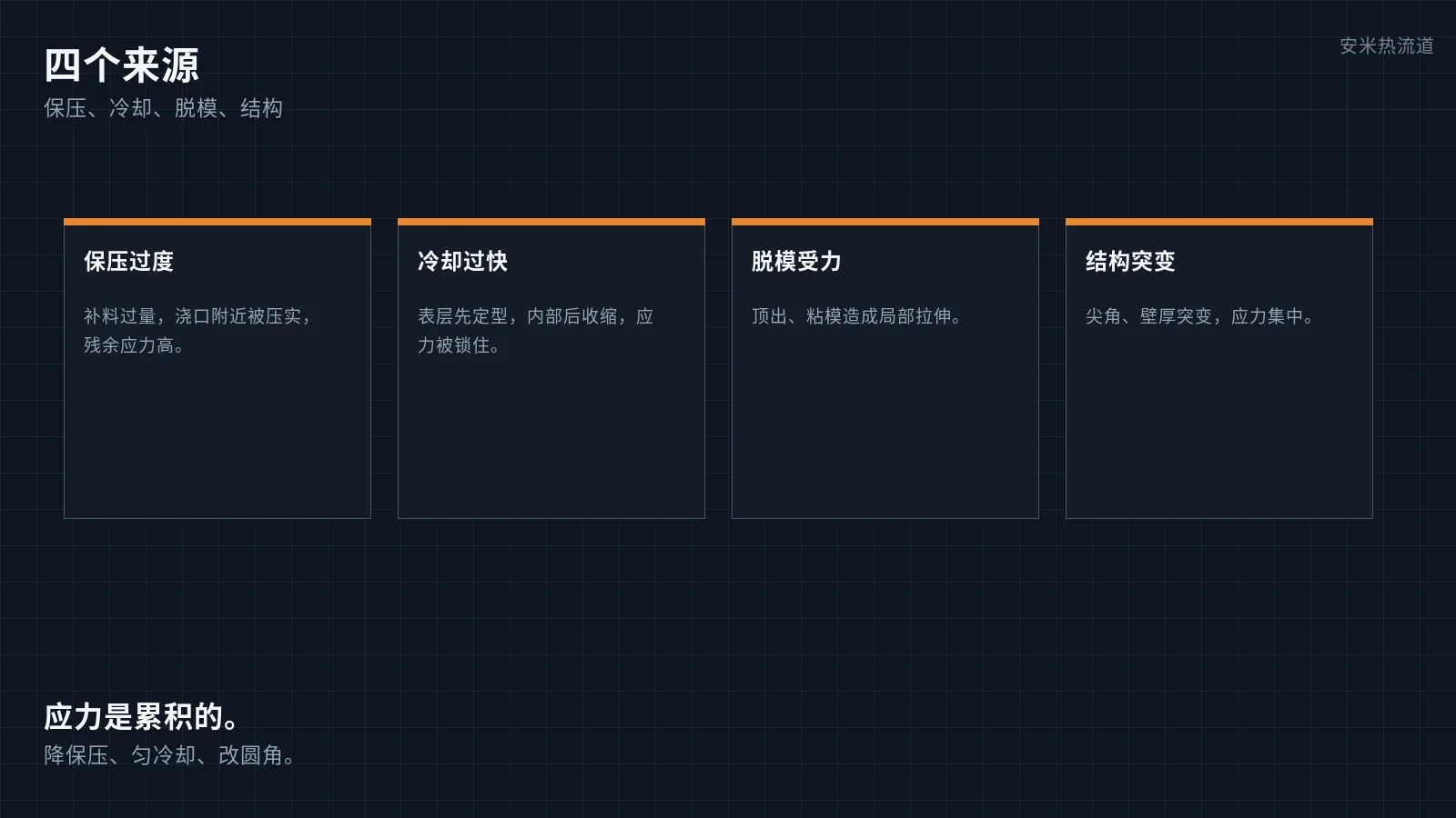
Excessive holding pressure: Over-packing leads to high density and stress near the gate.
Excessive or uneven cooling: The surface layer cools and solidifies first, while the interior continues to shrink, trapping stress in the part.
Demolding forces: Mold sticking, insufficient draft angle, or unbalanced ejection cause localized stretching.
Structural discontinuities: Stress concentrations occur at sharp corners, abrupt wall thickness changes, and rib roots.
Material and drying: PC, PMMA, and PSU are stress-sensitive and become more brittle when moisture is present.
III. Differentiate from Brittle Fracture and Stress Whitening
Brittle fracture occurs instantly under load, producing a flat fracture surface.
Stress whitening is surface whitening without cracking.
Internal stress cracking appears with delay; cracks are slender and propagate along the stress direction.
IV. Responsibility Allocation
Injection molding machine: hold pressure and time, cooling time.
Mold: mold temperature, draft angle, ejection, structural fillets.
Hot runner: gate temperature and sealing timing affect packing volume near the gate.
V. Solutions
Reduce holding pressure; set holding time based on sealing moment; do not use extended holding to compensate for dimensions.
Increase mold temperature and slow down cooling to align internal and external shrinkage.
Improve demolding: increase draft angles, polish surfaces, balance ejection.
Use fillets and wall thickness transitions in your design to reduce stress concentration.
Stress-relieve molded parts per material requirements.
Clarify the boundary: stress cracking is due to stress release, not material failure; first reduce pressure and ensure uniform cooling before considering material changes.
Conclusion
Internal stress is a chronic issue. Reduce holding pressure, ensure uniform cooling, and modify fillet radii simultaneously.
For further verification, please provide the mold 2D layout drawing. We will check gate positions and cavity temperatures item by item based on the layout, then provide a solution and quotation after confirmation.
MATCHED BY MATERIAL AND DEFECT
The article covers gate marks or residue on cosmetic surfaces; check VG for a flush break and pin maintenance.
Register for a selection review and quote
Submit part, mold, and material details. Our engineers will evaluate the gate solution per part and provide a quote.
Upload a 2D layout drawing using the form.
Online selection and quote
Scan to register