
Ejector Whitening: White Marks at Ejector Pin Locations, Not Gates
Injection Molding Encyclopedia7 min read
On this page
White spots or marks appear at ejector pin locations; they cover a small area but have clear boundaries and are more noticeable on thinner parts. This is stress whitening.
This article clarifies the differences between stress whitening, gate whitening, and drag marks, and explains why ejection parameters can only mitigate, not resolve, the issue.
1. Location
Ejector pin positions: White spots correspond one-to-one with ejector pins; this is the most direct diagnostic criterion.
Deep cavities and thin walls: Under the same ejection force, thinner sections are more prone to whitening.
2. Root Causes
High demolding resistance: Caused by strong shrinkage grip, insufficient draft angle, or vacuum formation due to surface adhesion.
Unbalanced ejection: Insufficient number or area of ejector pins, causing localized stress concentration.
Insufficient cooling: Ejection temperature is too high; material strength is insufficient to withstand ejection.
Excessively thin structure: Thin walls and deep cavities lack sufficient stiffness in the ejection direction.
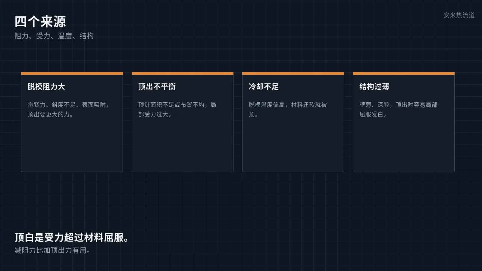
III. Distinction from Gate Whitening and Scuffing
Gate whitening occurs around the gate, caused by shear and seal-off.
Scuffing appears as streaks on the demolding surface, accompanied by mold sticking.
Ejection whitening presents as fixed-position white spots at ejector pin locations, directly related to ejection force.
IV. Responsibility Allocation
Mold aspect: Draft angle, ejector pin layout and area, cavity surface finish, and air venting.
Injection molding machine parameters: ejection speed and stroke, cooling time.
Hot runner factors: gate temperature affects local strength during demolding but does not change the force at ejector pin positions.
5. Solutions
First, reduce demolding resistance: increase draft angle, polish the cavity, and add air venting if necessary.
Increase the number or area of ejector pins to distribute ejection force.
Extend cooling time or reduce mold temperature to ensure adequate part strength during ejection.
Use staged ejection: start slowly, then accelerate to reduce peak impact.
Clarify the boundary: stress whitening is a force issue; increasing ejection force only worsens it. Reduce resistance, do not increase force.
Conclusion
The location of whitening provides the answer: white spots appear at ejector pin positions. Reducing resistance and distributing ejection force are more direct than adjusting ejection speed.
For further verification, please provide the 2D mold layout drawing. We will check each gate and cavity temperature item by item against the layout, then confirm the solution and quotation.
MATCHED BY MATERIAL AND DEFECT
The article covers gate marks or residue on cosmetic surfaces; check VG for a flush break and pin maintenance.
Register for a selection review and quote
Submit part, mold, and material details. Our engineers will evaluate the gate solution per part and provide a quote.
Upload a 2D layout drawing using the form.
Online selection and quote
Scan to register