
Insulation Margins for PPS Parts on 800V Platforms
Material Applications16 min read
On this page
New energy vehicles increase voltage from 400V to 800V, doubling the electric field stress on the same component. Insulation design now requires simultaneously evaluating material properties, structural geometry, and contamination levels—not just selecting a flame-retardant material.
PPS is widely used in high-voltage components such as busbar brackets, HV connector housings, and battery module insulators. It offers heat resistance, low water absorption, dimensional stability, and good CTI. However, safety margins are not guaranteed automatically.
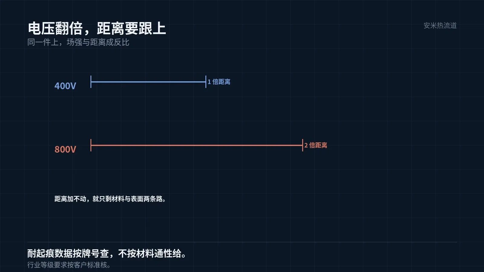
Doubling Voltage Does Not Double Safety Margins
Electric field strength is proportional to voltage and inversely proportional to distance. Increasing the voltage from 400V to 800V doubles the field strength if the distance remains unchanged. The distance must increase accordingly to maintain safety margins.
If increasing distance isn't feasible, consider two alternatives: switch to materials with better tracking resistance or control surface contamination. Both options are more cost-effective than increasing distance but require more effort to implement.
PPS offers upper-mid-range tracking resistance among engineering plastics; actual values vary by grade and cannot be generalized by material type. Industry standard grade requirements must be verified against customer specifications. We do not include codes or numerical values in our proposals.
Therefore, asking "Can PPS handle 800V?"?" is the wrong question. The correct questions are: What is the creepage/clearance distance for this part? What is the pollution degree? What are the tracking data for the specific material grade?
Low water absorption is its key advantage at this level.
PPS exhibits extremely low water absorption, setting it apart from PA46 and PA9T in high-voltage applications. Water absorption creates conductive surface paths, induces dimensional changes, and reduces creepage distance.
PA46 exhibits significantly higher water absorption; PA9T absorbs 0.19%. Under long-term operation in humid environments, the dimensions and surface conditions of both change, while PPS shows the least variation.
Dimensional stability also affects creepage distance for high-voltage components, which is determined by the physical structure. If dimensions shift, so does the clearance. An expansion of 0.1 mm after three years can exhaust the design margin.
A shrinkage of 0.3%/0.8% and a mold temperature of 150°C ensure complete crystallization. These two factors form the foundation for initial precision and long-term stability.
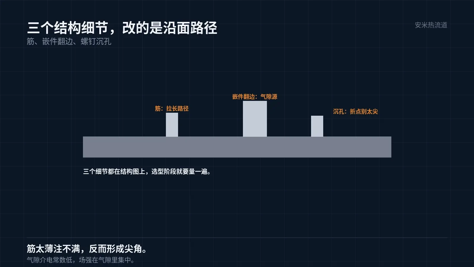
Three Structural Details
First, ribs. Ribs extend the surface path; however, if they are too thin, they may not fill completely, creating sharp corners that concentrate the electric field. Rib width and height must be calculated together with wall thickness.
Second, the flange of metal inserts creates air gaps at the interface with the plastic part. These gaps have low dielectric constants, leading to electric field concentration and initiating partial discharge.
Third, screw counterbores. The depth and diameter of the counterbore determine the inflection points on the surface path. If these points are too sharp, tracking starts there.
These three dimensions are specified in structural drawings, not material data sheets. They must be drawn and measured during the selection phase, prior to mold fabrication.
Contamination is a field issue, not a design issue.
Field failures of high-voltage components are primarily caused by contamination: flux residue, cleaning agent residue, dust, and condensation. These contaminants are absent in the lab but occur daily in vehicles.
PPS is chemically resistant, but chemical resistance does not prevent surface contamination. Surface roughness, mold release residue, and exposed glass fibers all promote contaminant adhesion. Mold polishing and post-treatment must be strictly controlled.
Cleaning methods must also be matched. Ultrasonic cleaning with alkaline agents removes flux but alters surface condition; plasma treatment improves the surface but has limited durability. Choose based on your actual production line conditions.
We observed batches that passed lab tracking tests but failed three months after vehicle installation. Cross-section analysis revealed carbonization paths originating from exposed glass fibers near the gate—areas where mold polishing was insufficient.
Molding: Melt Temperature Limit and Gate
PPS melt temperature must not exceed 360°C; nozzle: 310–320°C; mold temperature: 150°C. Overheating causes degradation, leading to poor flow and black spots on parts. In high-voltage components, black spots act as electric field concentration points.
Dry at 140°C for 3 hours or 120°C for 5 hours. High-voltage components often have uneven wall thickness; insufficient drying increases the risk of foaming in thicker sections. Bubbles create air gaps that can lead to partial discharge.
Use SD Series only for gates. High-voltage components have large dimensions and long flow paths; the SD series provides adequate flow capacity. Do not use TP, VG, or PVG: shear stress and stagnation at valve gates are unsuitable for PPS.
Pin-point gate: φ0.8–1.2 mm (use the larger value for large parts). Vent groove depth: 0.005–0.008 mm; for large parts with large cavities, venting capacity must be calculated based on flow length and cannot simply copy the depth used for small parts.
Verification: Four steps. None can be skipped.
Step 1 Material: Retrieve tracking data by grade; leave blank if unavailable. Step 2 Structure: Measure creepage distance per drawing, then verify on the physical part. Step 3 Surface: Perform contamination tests following production line cleaning procedures. Step 4 Assembly: Conduct withstand voltage, partial discharge, and temperature cycling tests.
Temperature cycling is the step most likely to be skipped in the four-step process. High-voltage component failures often occur after cycling due to interface loosening, increased air gaps, and reduced partial discharge inception voltage. This step cannot be detected under constant temperature and humidity conditions.
Send us the part drawing, voltage rating, pollution degree, and cleaning process. We'll verify creepage and clearance distances and surface conditions, then provide a quote after confirming the material and gate solution.
MATCHED BY MATERIAL AND DEFECT
This article covers stringing, drooling, clogging, and high-heat resins; refer to SD for gate freeze and break-off.
Register for a selection review and quote
Submit part, mold, and material details. Our engineers will evaluate the gate solution per part and provide a quote.
Upload a 2D layout drawing using the form.
Online selection and quote
Scan to register