
How Much Insulation Margin Remains for PA9T on 800V Platforms?
Material Applications16 min read
On this page
High-voltage components for new energy applications feature increasingly compact structures and higher voltages. For the same creepage distance, electric field strength on a 800V platform is double that of 400V; any surface contamination increases tracking risk.
PA9T is used in high-voltage components: its 300°C melting point withstands heat, and its 0.19% water absorption ensures dimensional stability in humid conditions. However, for insulation, it provides a baseline, not a guarantee.
How Tracking Works
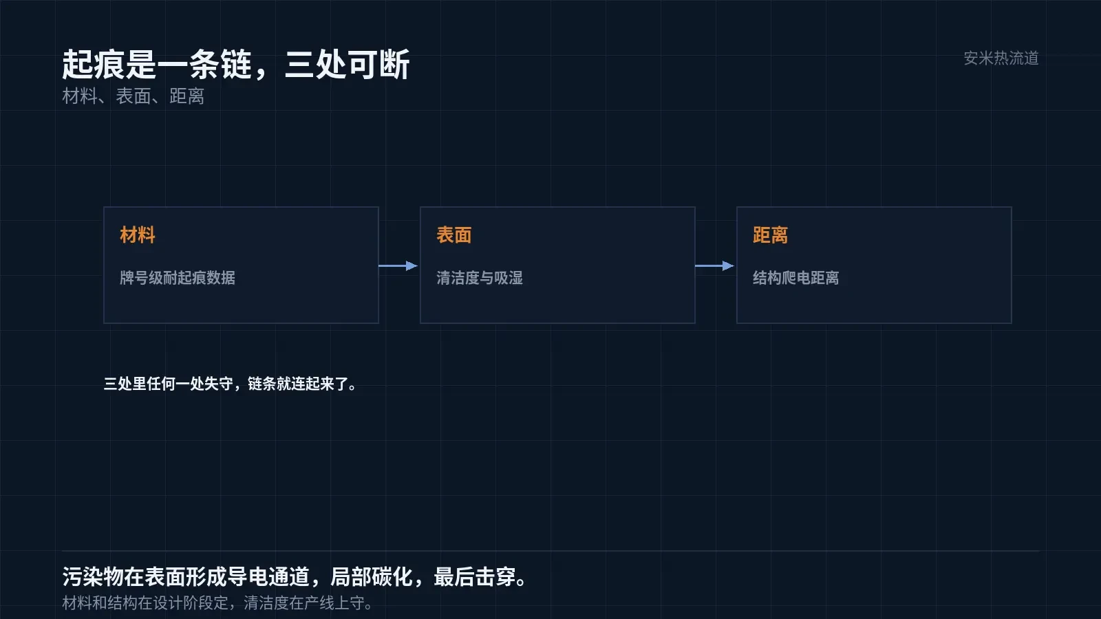
Tracking leakage is a surface phenomenon: contaminants form conductive paths on the component surface, causing localized current heating and carbonization. Carbonization further increases path conductivity, ultimately leading to breakdown.
This chain can be interrupted at three stages: material tracking resistance, component surface cleanliness, and structural creepage distance. Material and structure are defined during design; cleanliness is maintained on the production line.
PA9T tracking resistance must be verified by grade, not inferred from general material properties. Flame-retardant and general-purpose grades have distinct data sets; switching grades requires re-verification.
Basic material selection discipline: Do not include data in proposals if it is absent from datasheets. If inclusion is necessary, obtain grade-specific data or conduct tests.
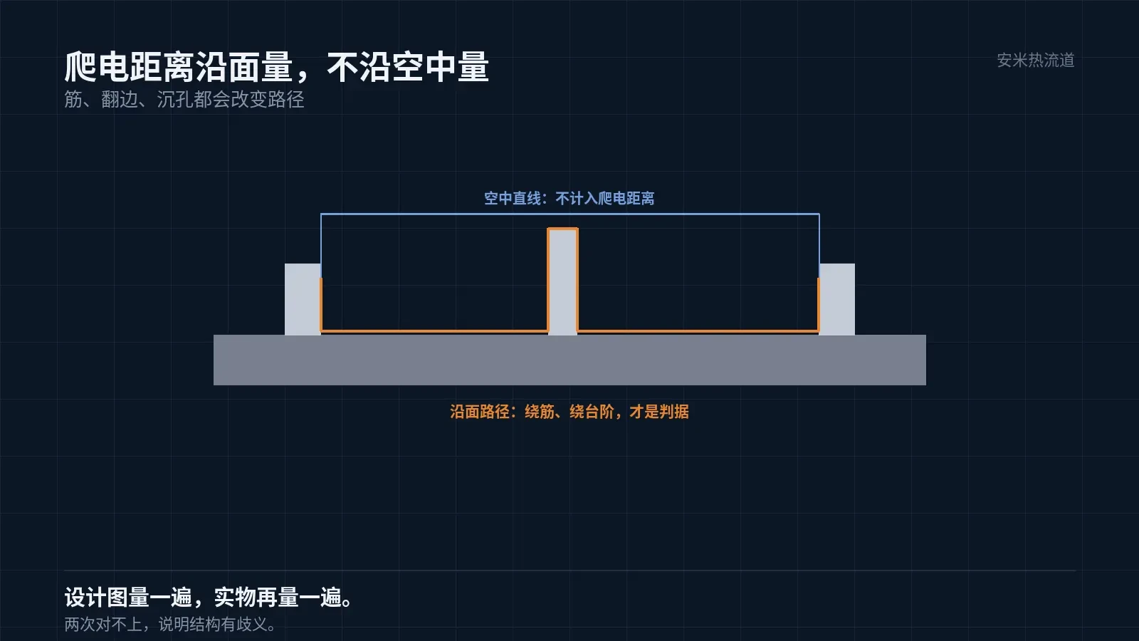
Structural detail: Creepage distance is measured along the shortest path. Rib height, terminal flanges, and screw counterbores affect this path. Verify the measurement on both the design drawing and the physical part; discrepancies indicate structural ambiguity.
Effect of Water Absorption on Insulation
PA9T water absorption is 0.19%, low but not zero. Moisture absorption reduces surface resistance, lowering the tracking threshold.
In humid thermal environments, insulation performance degrades significantly compared to dry conditions. Validating only under dry conditions without humid thermal testing is the most common failure mode for these parts.
Recommended validation sequence: dry-state insulation, insulation after humid thermal aging, insulation after temperature cycling, and tracking resistance. If the first three tests fail, the fourth test will not yield a conclusive result.
Record dimensions at each step. Moisture absorption changes dimensions, which affects creepage distance and requires recalculating insulation conclusions.
Temperature cycling is often skipped due to its duration. However, high-voltage failures frequently occur after cycling: loose interfaces, increased air gaps, and partial discharge that cannot be detected under constant temperature and humidity.
Do not discard components after tracking tests; section them to analyze the depth and direction of carbonization paths. Path orientation determines whether the cause is surface contamination or structural tip discharge, guiding different remediation strategies.
Temperature Considerations
High-voltage component temperatures result from Joule heating caused by high current and thermal radiation from nearby parts. Operating long-term around 120°C, with higher short-term peaks, is a typical condition.
PA9T has a melting point of 300°C, providing a margin of over 100°C above its long-term service temperature. While this margin is sufficient, it is not unlimited; if local hotspots near the part consistently exceed the material's continuous use temperature, aging will accelerate.
Barrel temperatures are 280–320/285–330/290–340°C, and nozzle temperature is 300–350°C. At these settings, control melt residence time to prevent black spots and color changes caused by degradation.
To determine actual part temperature exposure, do not rely solely on datasheets: apply thermal labels to the part surface and record peak values during a full operational cycle. A discrepancy of more than 20°C between peak values and datasheet specifications is common.
Gate and Electric Field
For this material group, only the SD open hot tip is recommended. Electric fields tend to concentrate near the gate in high-voltage components; gate marks, skinning, and flash can alter the local electric field.
The SD mark is a small raised feature with a fixed position defined during design, enabling simple trimming. In contrast, the mechanical mark location for VG is harder to control and less suitable for high-voltage components.
Multi-cavity molds require careful thermal balance. If the temperature difference between cavities exceeds 10°C, crystallinity varies, leading to inconsistent insulation performance after moisture absorption.
If metal inserts are near the gate, avoid air gaps at the insert-plastic interface. Air gaps can cause partial discharge under high voltage—a failure mode that is not visible from the exterior.
Flame Retardancy and Structure
Adhere to customer flame retardant standards. Adding flame retardants may reduce mechanical properties and heat resistance. When switching grades, re-validate processing windows; do not reuse parameters from general-purpose grades.
Structural measures include adding ribs to increase creepage distance, increasing spacing between terminals and the housing, and avoiding sharp corners. These three approaches are more cost-effective and reliable than changing materials.
Potting or coating adds a protective layer but cannot substitute for substrate insulation or mask surface contamination. Address the substrate and surface first, then consider potting.
Verification and Records
Keep three samples at each of the four checkpoints, labeled with operating conditions and date. Record dimensions, insulation, and appearance together. Future similar parts can reference these records directly, eliminating one round of verification.
Records must specify voltage platform, creepage distance, and pollution degree. Data cannot be reused without these three items.
If the material, mold, or structure changes, verification must be repeated. This is not procedural redundancy but a practical requirement for high-voltage components.
Please provide the voltage platform, creepage distance, part type, number of cavities, and customer-required standards. We will review based on temperature and insulation criteria and provide a quote once the solution is confirmed.
MATCHED BY MATERIAL AND DEFECT
This article covers stringing, drooling, clogging, and high-heat resins; refer to SD for gate freeze and break-off.
Register for a selection review and quote
Submit part, mold, and material details. Our engineers will evaluate the gate solution per part and provide a quote.
Upload a 2D layout drawing using the form.
Online selection and quote
Scan to register