
Can Low-Warp PA9T Handle Increasingly Fine-Pitch Connectors?
Material Applications17 min read
On this page
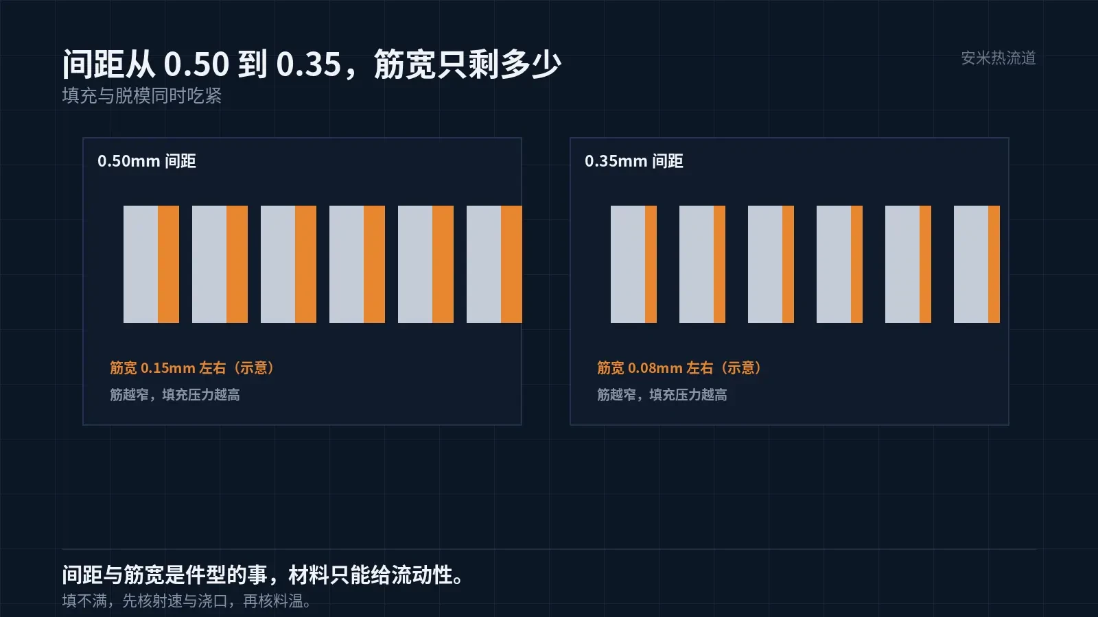
Board-to-board connectors in smartphones, tablets, and laptops have pitches shrinking from {0.5mm to 0.35mm,, with terminal spacing barely wider than a human hair. As pitch density increases, warpage of the molded component becomes the primary yield killer.
PA9T belongs in this size range not for its strength, but because it absorbs little moisture and maintains stable shrinkage. However, low warpage isn't achieved by the material alone; it results from jointly optimizing material selection, part geometry, gate design, and mold temperature.
At what pitch density does difficulty start?
At a 0.5 mm pitch, rib width remains around 0.15mm,, enabling feasible mold fabrication and material filling. At a 0.35mm pitch, rib width drops to approximately 0.08mm,, making simultaneous filling and demolding challenging.
For materials in this size range, the primary requirement is flowability. Without proper melt flow, short shots occur, resulting in immediate scrap. The second key requirement is low warpage, as warped parts cannot be mounted onto the board.
PA9T barrel conditions are 280–320/285–330/290–340°C, with nozzle temperatures at 300–350°C, falling within the high-temperature range. The combination of high temperature and low viscosity ensures complete filling of thin ribs.
These values reflect OEM-specified ranges. Specific settings for individual machines or molds must be determined through short-shot tests. The ranges indicate boundaries, not fixed setpoints.
Warpage is calculated using four factors
The first factor is material: PA9T shrinkage is 0.3%/0.9%, with a threefold directional difference. This variation results from glass fiber orientation and cannot be eliminated through process adjustments.
The second factor is part geometry: align long edges with flow direction and keep short edges perpendicular. Moving the gate changes orientation. Fine-pitch parts have high aspect ratios, making them especially sensitive to this factor.
The third factor is the gate: positioned centrally, it creates the lowest pressure at the weld line. Differential shrinkage between the weld line and the ends initiates warpage.
The fourth factor is mold temperature. High temperatures promote full crystallization and stable shrinkage but slow cooling; low temperatures cause surface skin freezing first, leading to internal post-shrinkage and sinking. No OEM-recommended mold temperature values are provided; verification must rely on first-article data.
Implications of Tg 125°C
PA9T has a Tg of 125°C. In consumer electronics, this means two things: during reflow soldering, parts exceed Tg and lose rigidity; during normal use, parts stay about 100°C below Tg, maintaining dimensional stability.
Exceeding Tg during reflow is not critical; the risk stems from insufficient support while the component remains above Tg for tens of seconds. At least one of the following must be used: fixtures, trays, or hold-down bars.
Dimensional stability at room temperature is achieved through low moisture absorption: a 0.19% absorption rate ensures minimal swelling in humid conditions. Consumer electronics assembly tolerances are often ±0.05mm;—this factor directly determines whether adjustment-free assembly is feasible.
Fine-pitch components have another hidden dimensional source: stress from terminal insertion. Pressing terminals into place locally expands the plastic part; incomplete elastic recovery after cooling causes hole position deviation. This requires calculation based on both terminal interference and wall thickness, rather than relying solely on mold compensation.
Gate and Marks
For this material group, only the SD Series open-tip hot runner is recommended. Gate locations for fine-pitch parts are typically at part edges or between terminals due to extremely limited space.
In tight spaces, the VG Series valve pin lacks sufficient actuation room. The pin cannot fully close before the melt semi-solidifies, leading to tearing instead of clean shearing. Residual skin falling between terminals poses a short-circuit risk.
The SD Series leaves a small bump mark. Fine-pitch parts require precise control of its position and height: it must be located in a non-contact area and remain below the terminal surface. These requirements are established during mold design review; trial molding allows only minor adjustments.
Gate diameter must be customized for each part. Oversized gates produce low shear but leave larger marks; undersized gates cause high shear and accelerate gate wear. Pin-point gates typically start at φ0.8mm and are optimized based on filling performance and mark quality.
In fine-pitch applications, mold wear occurs faster than in conventional parts. Small gates, high shear forces, and glass fiber content accelerate gate wear, altering the effective flow area. Filling behavior shifts after hundreds of thousands of cycles. Mold designs should incorporate replaceable gate inserts.
Replace inserts proactively, not after defects occur. Set intervals based on shot count and short-shot curves: replace the insert if the short-shot location retreats by 10% compared to initial records under identical parameters.
Terminal plating also affects the molded part: uneven plating thickness causes uneven frictional heat during insertion and extraction, leading to localized temperature spikes that accelerate hole wear. Adding this check to incoming inspection prevents these issues.
Verification and Documentation
First, measure warpage: place the part on a granite surface plate and record deviations at the four corners and center. For fine-pitch parts, allowable warpage is typically tens of microns; exceeding this limit will prevent proper mounting.
The second metric is terminal coplanarity: the difference between the highest and lowest terminal points. This parameter better indicates assembly yield than overall warpage.
The third data set covers insertion and extraction forces: with tight pitch, the process window is narrow, so any dimensional variation in the part can cause force to exceed specifications.
All three data sets must come from the same batch, cavity number, and furnace run. Re-measure when switching batches or molds; do not use prior batch data as a baseline.

Please provide the pitch, terminal count, part length/width, number of cavities, and current gate type. We will verify the solution against both warpage and gate vestige criteria before providing a quote.
MATCHED BY MATERIAL AND DEFECT
This article covers stringing, drooling, clogging, and high-heat resins; refer to SD for gate freeze and break-off.
Register for a selection review and quote
Submit part, mold, and material details. Our engineers will evaluate the gate solution per part and provide a quote.
Upload a 2D layout drawing using the form.
Online selection and quote
Scan to register