
For High-Voltage Connectors Using PA46, Which Limits First: Insulation or Temperature Resistance?
Material Applications17 min read
On this page
For high-voltage components in new energy applications, as the voltage platform shifts from 400V to 800V, electric field strength doubles for the same creepage distance. While temperature resistance is often the primary material requirement, insulation frequently becomes the critical bottleneck.
PA46 plays a role in high-voltage connectors, but with limits: it handles temperature, while insulation depends on both grade and design. This article clarifies where that boundary lies.
After 800V, Distance Is Insufficient
As the voltage platform increases, higher field strengths are maintained across the same clearance and creepage distances. Structural distance increases are limited; the remainder must rely on material properties and surface conditions.
Surface condition encompasses cleanliness, moisture absorption, and contamination. Moisture absorption lowers surface resistivity and raises creepage risk, especially in humid, high-temperature environments.
Therefore, selecting materials for high-voltage components cannot rely solely on volume resistivity. It must account for insulation performance after moisture absorption and resistance to tracking. These factors must be verified by specific grade rather than inferred from general material properties.
Another constraint is space: as voltage rises, creepage distance must increase, but part size cannot expand. This forces thinner walls and more complex geometries, raising filling difficulty. This factor must be calculated during material selection—not discovered after molding when short shots occur.
Division of labor between PA46 and PPS in high-voltage components: PPS offers superior tracking resistance and dimensional stability, while PA46 delivers adequate toughness and temperature resistance at a lower cost. Selection is driven first by the customer's required tracking resistance rating, then by mechanical load requirements.
Temperature Resistance Addresses a Different Issue
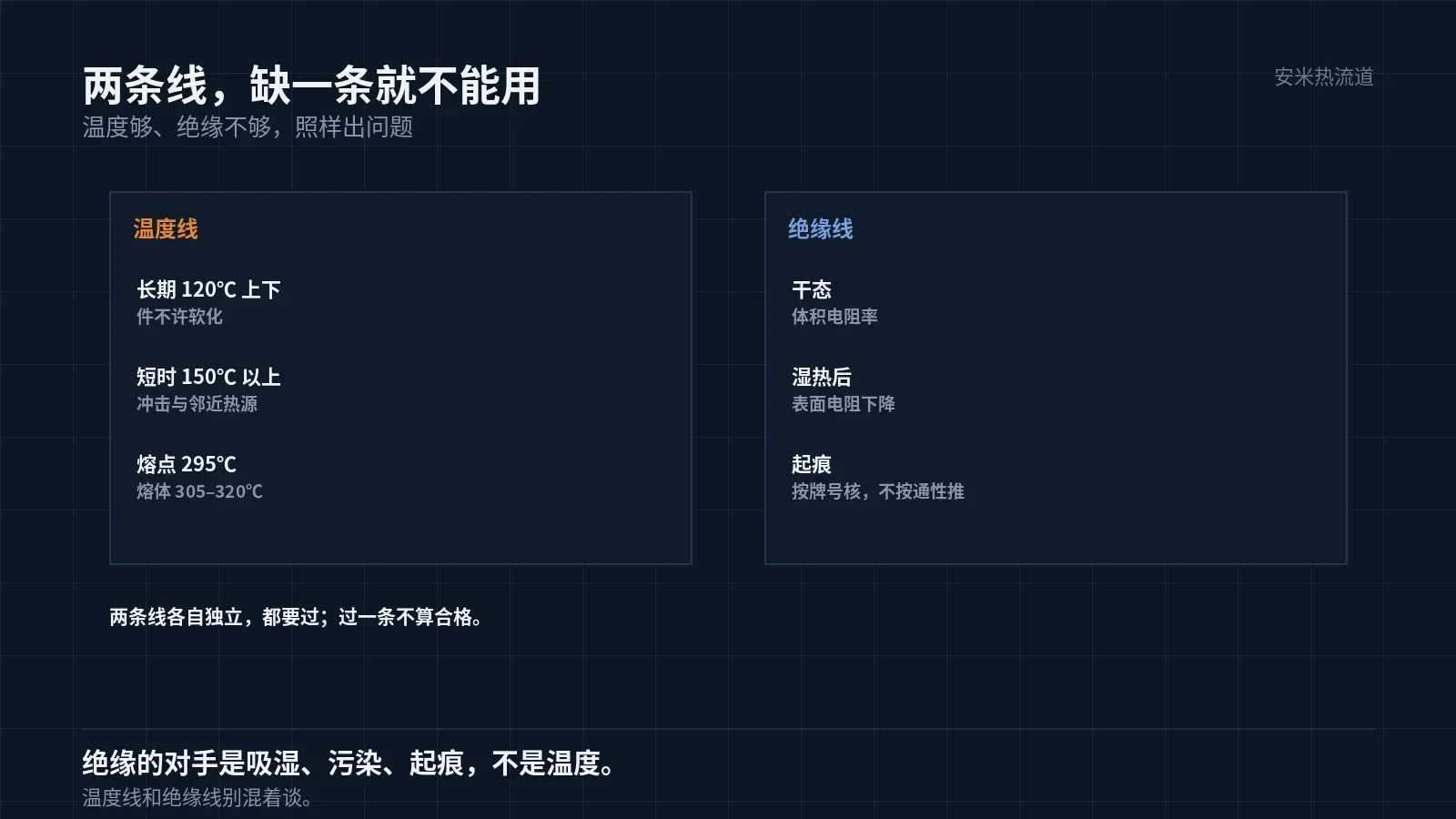
Temperatures near high-voltage connectors result from Joule heating caused by high currents and thermal radiation from nearby components. A common operating condition involves prolonged exposure around 120°C with higher short-term temperature spikes.
PA46 has a melting point of 295°C. The melt temperature must exceed 305°C, with an optimal range of 305–320°C. While this temperature profile supports its use in this application, its key advantage over PA66 is the higher melting point; however, it is not suitable for all positions.
Determine the actual temperature experienced by the part instead of relying solely on datasheets: apply thermal labels to the surface, run a full operational cycle, and record the peak temperature. Peak temperatures often differ from datasheet values by more than 20°C; selecting materials based on datasheets alone can lead to incorrect safety margins.
Temperature resistance and insulation are independent requirements. Inadequate temperature resistance leads to softening and deformation; inadequate insulation causes tracking and breakdown. Both must be satisfied—failure in either renders the material unusable.
Trade-offs between Glass Fiber and Flame Retardancy
30% glass fiber enhances strength and dimensional stability but introduces two side effects: fiber orientation leads to anisotropic shrinkage, while exposed fibers compromise surface insulation.
Shrinkage is 0.4%/1.1%, with a directional difference of nearly three times. Elongated high-voltage components are most sensitive to this variation; length-direction tolerances and assembly clearances must be calculated accordingly.
Select flame-retardant grades based on customer requirements. Flame retardants impact mechanical properties and heat resistance; therefore, flame-retardant grades do not share the same parameters as general-purpose grades. Processing windows must be re-evaluated when switching grades.
Temperature rise must be calculated alongside the current-carrying cross-section. For the same terminal, a slight increase in contact resistance can cause a significant temperature spike, eroding the material's safety margin. Contact resistance is determined by terminal design and plating, not the base material; do not confuse these factors.
Shrinkage difference usage: align long edges with the flow direction and reserve short edges for the transverse direction. Changing the gate position alters orientation, requiring recalculation of the dimension chain. This effect is especially pronounced in elongated housings for high-voltage components.
Gate and Electric Field
For this material group, only the SD open hot tip is recommended. Electric fields often concentrate near the gate of high-voltage components; gate marks, skinning, and flash can alter the local field.
The SD mark is a small raised feature with a fixed position defined during design, which simplifies downstream trimming. Valve pin mechanical marks are more difficult to control and less suitable for high-voltage components.
In multi-cavity molds, monitor thermal balance across cavities. If the temperature difference exceeds 10°C, crystallinity varies, leading to inconsistent insulation performance after moisture absorption.
Validation Must Include Damp Heat Test
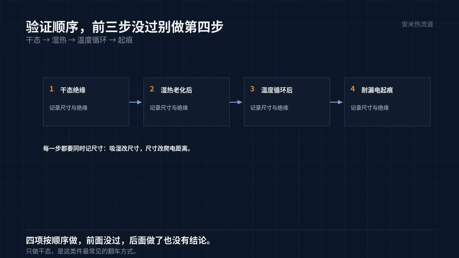
High-voltage components cannot be validated using dry-state testing alone. The most common failure mode is passing dry-state insulation tests but failing after damp-heat exposure.
Validation sequence: dry-state insulation, post-damp-heat aging insulation, post-temperature cycling insulation, and tracking resistance. These four tests must be performed in order; if the first three fail, the fourth is meaningless.
Dimensions must also be measured at these checkpoints. Moisture absorption causes dimensional changes that alter creepage distances and require recalculation of insulation conclusions.
Surface cleanliness directly affects insulation. Mold release oil, fingerprints, and demolding residue can initiate tracking. Protection during packaging and transfer is essential, as this factor is often overlooked on the production line compared to in the lab.
Post-assembly potting or coating adds a protective layer but cannot replace substrate insulation or mask surface contamination. Address substrate and surface conditions before applying potting.
Documentation best practice: retain three samples per node, labeled with operating conditions and date; record dimensions, insulation, and appearance together. Future similar parts can reference this data to eliminate one verification cycle.
Please provide the voltage platform, creepage distance, part type, number of cavities, and applicable customer standards. We will evaluate the solution based on thermal and insulation requirements and submit a quote upon confirmation.
MATCHED BY MATERIAL AND DEFECT
This article covers stringing, drooling, clogging, and high-heat resins; refer to SD for gate freeze and break-off.
Register for a selection review and quote
Submit part, mold, and material details. Our engineers will evaluate the gate solution per part and provide a quote.
Upload a 2D layout drawing using the form.
Online selection and quote
Scan to register