
When Choosing PA46 for Industrial Connectors, Is Temperature Resistance or Dimensional Stability More Critical?
Material Applications17 min read
On this page
Industrial parts face more demanding conditions than automotive: cabinets run cool, yet components must operate continuously for over a decade while resisting humidity, oil contamination, and occasional short-circuit surges.
The most common mistake when switching materials for these parts is focusing only on heat resistance. If heat resistance is adequate but dimensional stability drifts, assembly issues arise after two years. For industrial parts, PA46's value comes equally from heat resistance and crystallization stability.
Three Long-Term Requirements for Industrial Parts
First, self-heating occurs due to continuous energization. Local temperatures near terminals can exceed the ambient cabinet temperature by more than 20°C; this heat is dissipated through structural design rather than material properties.
Second is damp heat. Industrial sites feature high humidity, and PA46 exhibits significant moisture absorption. Absorbed moisture leads to dimensional expansion and strength degradation, necessitating strict control of both drying and encapsulation processes.
Third is chemical exposure. Cutting fluids, lubricants, and cleaners are common in industrial environments. When selecting grades, verify the specific contact media instead of relying solely on generic chemical resistance data sheets.
Of these three conditions, damp heat is most easily overlooked. Samples may pass three-day lab tests but begin to drift six months after field deployment.
The roles of PA46 and PA9T in industrial parts are distinct: PA9T absorbs 0.19% moisture and offers superior dimensional stability, making it ideal for long components with tight tolerances; PA46 provides higher heat resistance, suited for parts near heat sources. Both materials use SD Series nozzles exclusively—no special gate considerations are needed.
Crystallization Stability Determines Final Dimensions After Two Years
Glass-filled PA46 exhibits a shrinkage of 0.4%/1.1%, representing nearly a threefold difference between directions. This disparity is magnified in elongated industrial connectors, making length-direction tolerance the most challenging to maintain.
Crystallinity is controlled by mold temperature. A stable mold temperature ensures consistent shrinkage; fluctuations cause dimensional drift in parts from the same mold.
The OEM does not provide recommended mold temperature values for industrial parts; this parameter must be validated against the customer's mold. For multi-cavity molds, closely monitor temperature differences between cavities. If the difference exceeds 10°C, dimensions will split into two groups.
To evaluate mold temperature stability without waiting for dimensional data: take 20 consecutive shots and weigh one part every five cycles. If weight variation exceeds 0.3%, crystallization is shifting—check the mold temperature before adjusting holding pressure.
Gate Type and Long Conditions
For this material group, AM Industry product files recommend only the SD open hot tip. TP, VG, and PVG are not recommended.
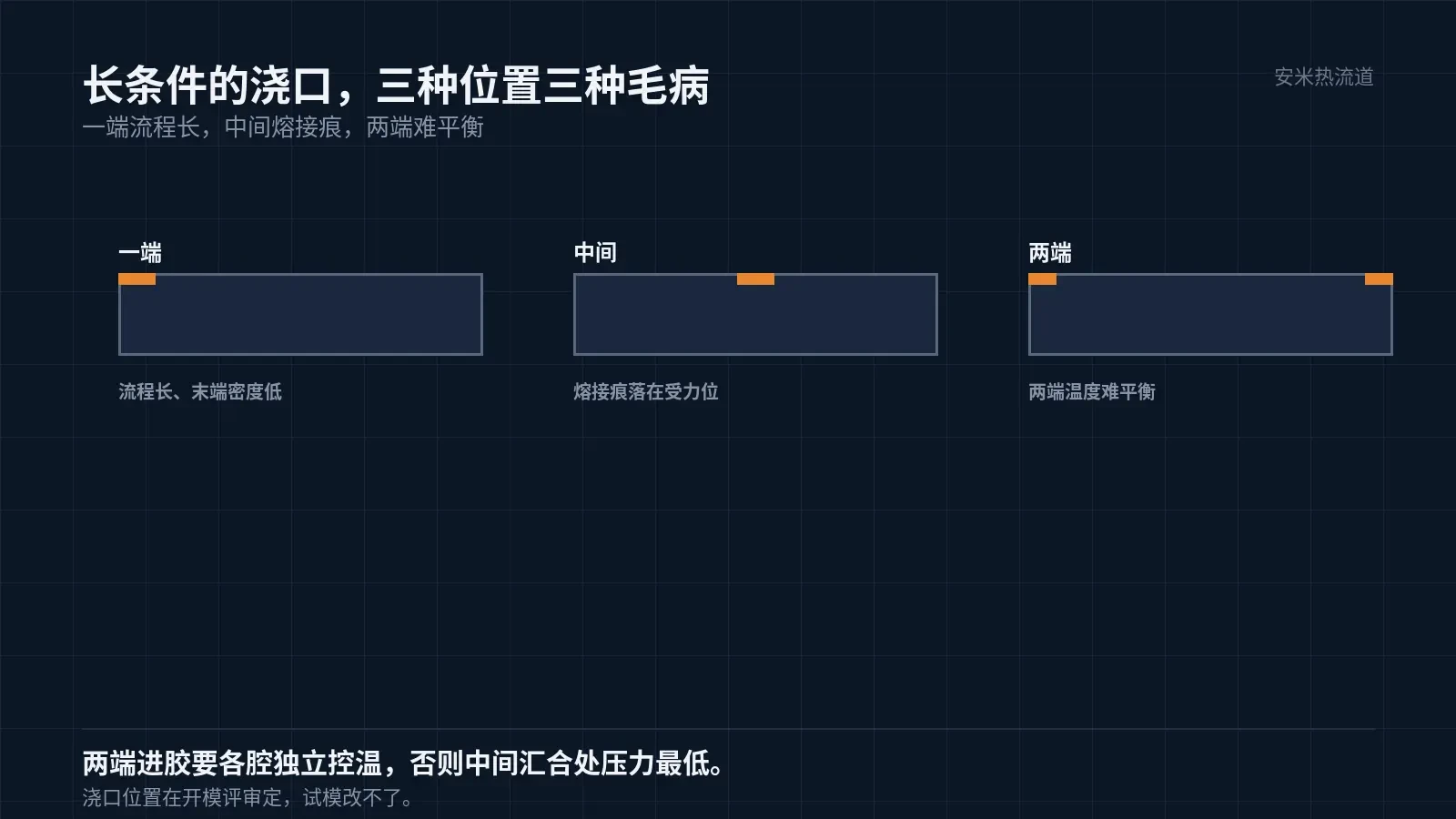
For elongated industrial connectors, gates are typically located at one end or in the center. End gating creates long flow paths and low pressure at the tip, exacerbating shrinkage variations; center gating positions weld lines in stress-critical areas.
The SD gate freeze-off relies on fast cooling at the gate, leaving a small bump mark. Since industrial parts have less stringent cosmetic requirements than consumer electronics, this bump is typically acceptable.
Venting method: Cut one vent at each weld line and flow end. Start with a depth of 0.005mm and increase by 0.001mm increments until slight flash appears, then step back. Jumping directly to 0.01mm causes both overflow and scorch marks.
If the part has multiple gates, control each gate's temperature independently. A 10-degree drop in one gate causes uneven filling and shrinkage at that end compared to others, resulting in dimensional chain errors originating from that point.
Gate location must account for assembly surfaces. Gating on an assembly surface affects fitment and may cause gaps after assembly; gating on non-assembly surfaces simplifies trimming. This decision is finalized during mold design review and cannot be changed during trial molding.
Two Data Sets to Monitor During Mold Trials
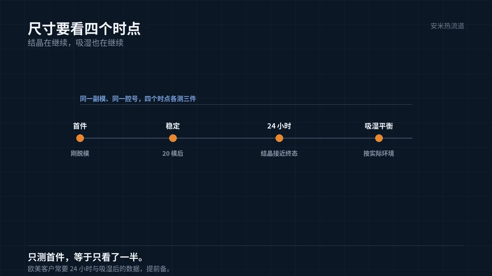
The first set comprises dimensional data: initial shot, post-stabilization, after 24 hours, and at moisture equilibrium. Presenting dimensions across these four time points in a single table clarifies the individual contributions of crystallization and moisture absorption.
The second set of metrics is electrical performance: insertion/extraction force and contact resistance. Dimensional drift impacts insertion/extraction force, making this metric more reliable than visual appearance.
Both datasets must originate from the same batch and mold number. If either changes, re-measure; do not use data from a previous batch as a baseline.
Additional note for long parts: Pressure drop peaks at the far end from the gate, leading to the lowest density in that region. Mechanical strength is typically lower there than near the gate; avoid placing load-bearing features in this area.
Flame retardant requirements for industrial parts must meet customer standards. When selecting flame-retardant grades, note that their melt processing window differs from general-purpose grades. Re-verify temperature and drying conditions; do not reuse parameters from general-purpose grades.
We recommend maintaining records by part number, including mold temperature, material temperature, cavity ID, dimensions at four time points, and insertion/extraction force. After collecting data from three batches, you can back-calculate the mold shrinkage compensation values.
Hidden Costs of Material Changeover
When switching from PA66 to PA46, raise the melt temperature above 305°C, reset drying conditions, and re-evaluate the mold gate and venting.
Parts with inserts require preheating. Cold inserts cause localized fast cooling, creating a stress ring that leads to cracking after demolding. Insert preheat temperatures should be determined by material and insert size, not by feel.
Vent depth is often overlooked. Due to the low melt viscosity of PA46, vents that are too deep cause flash, while those that are too shallow lead to burn marks; trial depths typically range from 0.005–0.008 mm.
Provide part geometry, length, number of cavities, contact media, and customer-specified dimensional tolerances. We will validate the solution against crystallization and shrinkage criteria before providing a quote.
MATCHED BY MATERIAL AND DEFECT
This article covers stringing, drooling, clogging, and high-heat resins; refer to SD for gate freeze and break-off.
Register for a selection review and quote
Submit part, mold, and material details. Our engineers will evaluate the gate solution per part and provide a quote.
Upload a 2D layout drawing using the form.
Online selection and quote
Scan to register