
Why Choose PA46 for Thin-Walled Consumer Electronics Parts?
Material Applications17 min read
On this page
In consumer electronics, PA46 is selected not for high-temperature resistance, but to enable thin walls and complex geometries in a single molding cycle. Common applications include smartphone mid-frame brackets, laptop connector sockets, and earbud charging case frames.
The challenge with thin-wall parts is filling, not material strength. Thin walls cause the melt to cool rapidly at the flow front, resulting in short shots, weld lines, and stress concentration. PA46's high flowability and crystallization rate meet these requirements perfectly.
When to Adjust Approach Based on Wall Thickness
For walls below 0.4mm,, standard glass-filled PA66 struggles to fill completely in a single shot, especially when flow lengths exceed 30mm.
PA46 has low melt viscosity and fast crystallization, allowing lower injection pressure for the same wall thickness and flow length. However, this results in a narrow process window, requiring precise control of injection speed and switchover point.
To decide whether to switch materials, evaluate two factors: flow-end filling at the thinnest section and maximum allowable injection pressure. Material selection is only critical if both constraints are limiting.
The differences between PA46 and PA9T are as follows: PA9T has a melting point of 300°C and water absorption of 0.19%, providing better dimensional stability but lower flowability than PA46. PA46 can mold thinner walls but has higher moisture absorption and a narrower processing window. Choose based on whether the thinnest wall or tightest tolerance is more critical.
Injection Speed: A Double-Edged Sword
Increasing injection speed reduces filling issues but increases shear heating. For PA46, 320°C is the maximum limit; shear-induced temperature rise at the gate cross-section can easily exceed this threshold.
Shear heat concentrates primarily at the gate exit. A common scenario for thin-wall parts is a set temperature of 310°C yielding an actual exit temperature of 325°C. Monitoring the exit temperature is more valuable than tracking barrel setpoints.
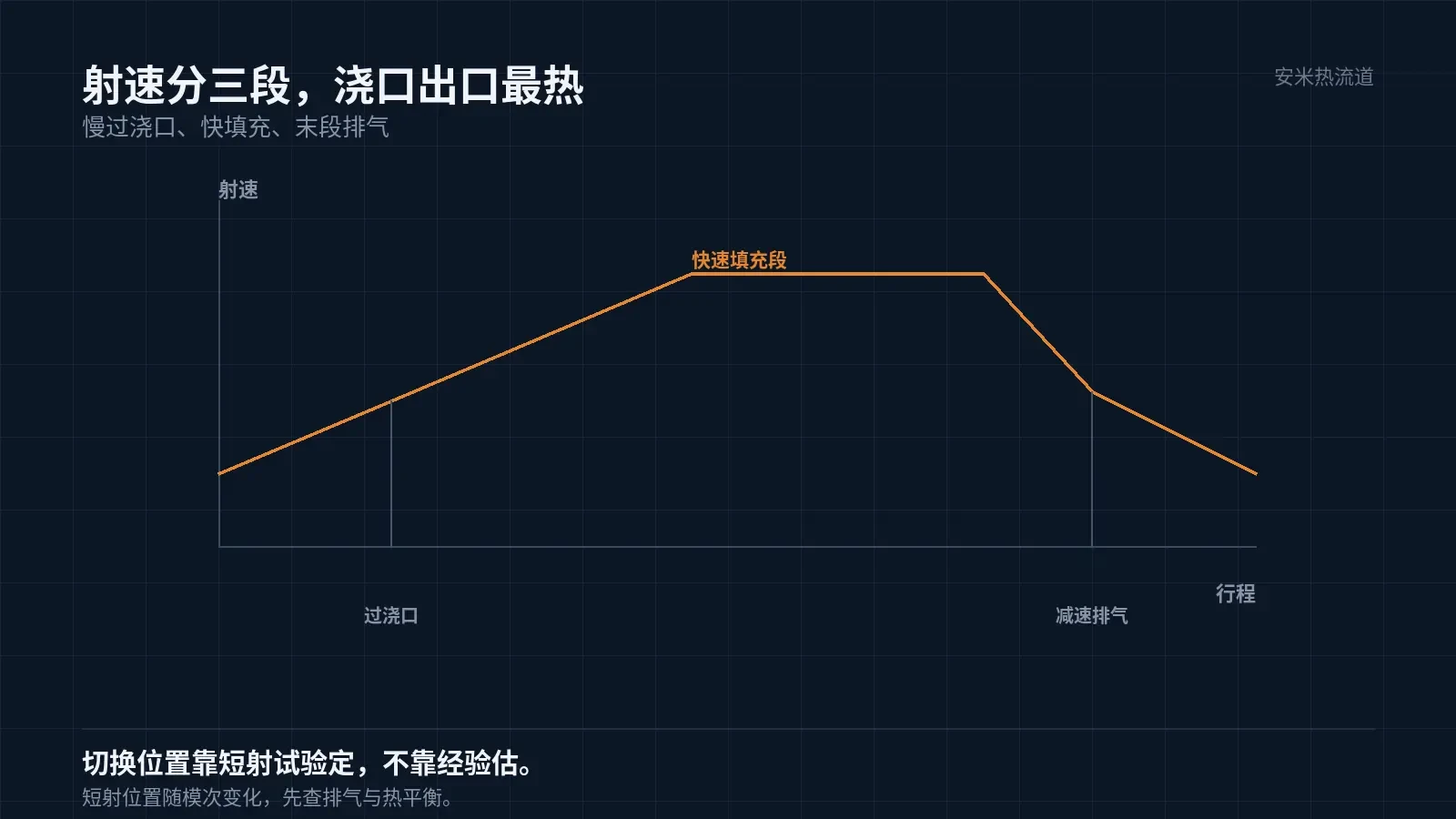
Injection speed must be staged: slow for the first stage to pass the gate, fast for filling in the second stage, and decelerated in the final stage for venting. Switch points are determined by short-shot tests, not estimated by experience.
A common misjudgment in thin-wall parts is attributing short shots to insufficient melt temperature. Short shots indicate a melt temperature issue only if they consistently occur at the end of the flow path where the temperature has dropped below 300°C. If the short shot location varies by cycle count, it indicates venting or thermal balance issues; increasing temperature will merely shift the problem elsewhere.
Exit Temperature Measurement: Run dry cycles without material, using either a contact probe at the gate exit or an infrared sensor on the sprue immediately after ejection. Both methods are acceptable; however, consistency is critical. Use the same machine, location, and method throughout to ensure comparable data.
Weld Line Location
Weld lines in thin-wall parts are nearly unavoidable; the goal is to move them to areas that are either invisible or non-load-bearing.
Gate position determines weld line location. In multi-gate systems, weld lines form where melt fronts converge; these zones have the lowest temperature and pressure, resulting in the weakest strength.
Consumer electronics cosmetic parts require that weld lines not appear on high-gloss surfaces. This constraint must be defined before mold fabrication; trial molding allows only minor adjustments and cannot change the overall layout.
Thin-wall part tolerance allocation must include margins: dimensional growth from moisture absorption, crystallization shrinkage, and mold wear often exceed half of the customer's specified tolerance band. Failing to account for this upfront guarantees part rejection during mass production.
Strength loss at weld lines can be estimated: lower melt temperature and pressure at the convergence point lead to greater loss. Therefore, after defining gate positions, use short-shot tests to verify convergence points instead of relying solely on mold flow analysis.
SD Series and Appearance
For this material group, only SD open-tip hot runners are recommended. Consumer electronics parts are small with multiple cavities and dense gate locations. The SD mark appears as a small bump, which is easier to manage than mechanical marks from valve gates.
Another advantage of SD is clean parting. On thin-wall parts, the gate area is often visible. Flash remaining after tearing requires manual trimming, which limits production capacity.
Valve gates can be used on thin-wall parts, but material selection must be careful. These materials' crystallization rates cause the melt to semi-solidify before the pin fully closes, turning cutting into tearing and resulting in both stringing and flash.
Dimensional Stability Matters More Than Strength
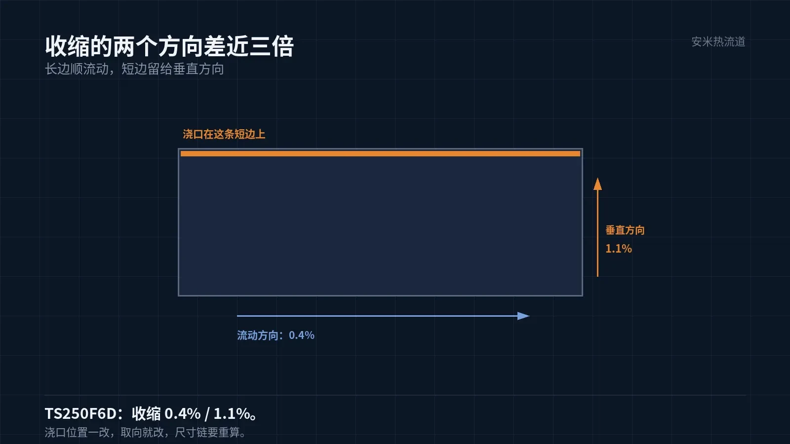
Assembly tolerances for consumer electronics are typically within ±0.05mm. PA46. Shrinkage is 0.4%/1.1%, with a directional difference nearly three times larger; part design must account for this differential.
Mold temperature has a greater impact on shrinkage than melt temperature. A high mold temperature promotes full crystallization, stabilizing shrinkage but increasing the risk of warpage; a low mold temperature cools the surface first while the interior shrinks later, leading to sink marks.
No recommended mold temperature values are provided by the original manufacturer; this parameter must be verified using actual molds and first-article data. Using a mold temperature curve from another project will cause dimensional mismatches.
Recommended trial molding sequence: 1) Perform short shots to confirm fill end; 2) Set three-stage injection speed; 3) Determine pack/hold switchover point; 4) Adjust mold temperature. Reversing this order invalidates prior data and wastes the entire trial run.
Recording Method: Take three samples per cavity. Label by cavity number and measure at the first shot, after 4 hours, and after 24 hours. Plot all three data sets on one chart to identify which cavity deviates, the deviation magnitude, and how it changes over time.
Send us the minimum wall thickness, flow length, number of cavities, appearance requirements, and current gate type. We will verify the solution based on filling and witness marks, then provide a quote upon confirmation.
MATCHED BY MATERIAL AND DEFECT
This article covers stringing, drooling, clogging, and high-heat resins; refer to SD for gate freeze and break-off.
Register for a selection review and quote
Submit part, mold, and material details. Our engineers will evaluate the gate solution per part and provide a quote.
Upload a 2D layout drawing using the form.
Online selection and quote
Scan to register