
What Specific Temperature Range Does PA46 Address in Automotive Connectors?
Material Applications16 min read
On this page
In the engine bay, a component is located near the cylinder block but not on the exhaust side. The ambient temperature stays around 130°C long-term, with short-term peaks exceeding 150°C. PA66 components in this area begin to embrittle after two to three years.
Switching to PA46 enables the same location to withstand these conditions. However, changing materials involves more than just emptying the hopper; you must also adjust the melting point, melt temperature, shrinkage, and gate type accordingly. This article explains how these four factors are applied to automotive parts.
First, Identify the Temperature Range
Automotive part temperatures should be evaluated in three segments: ambient temperature, self-heating, and exposure to welding or coating ovens. Most connector bodies are subject only to ambient temperature and self-heating; sensor housings and ignition coil bobbins also experience additional heat rise from the coils.
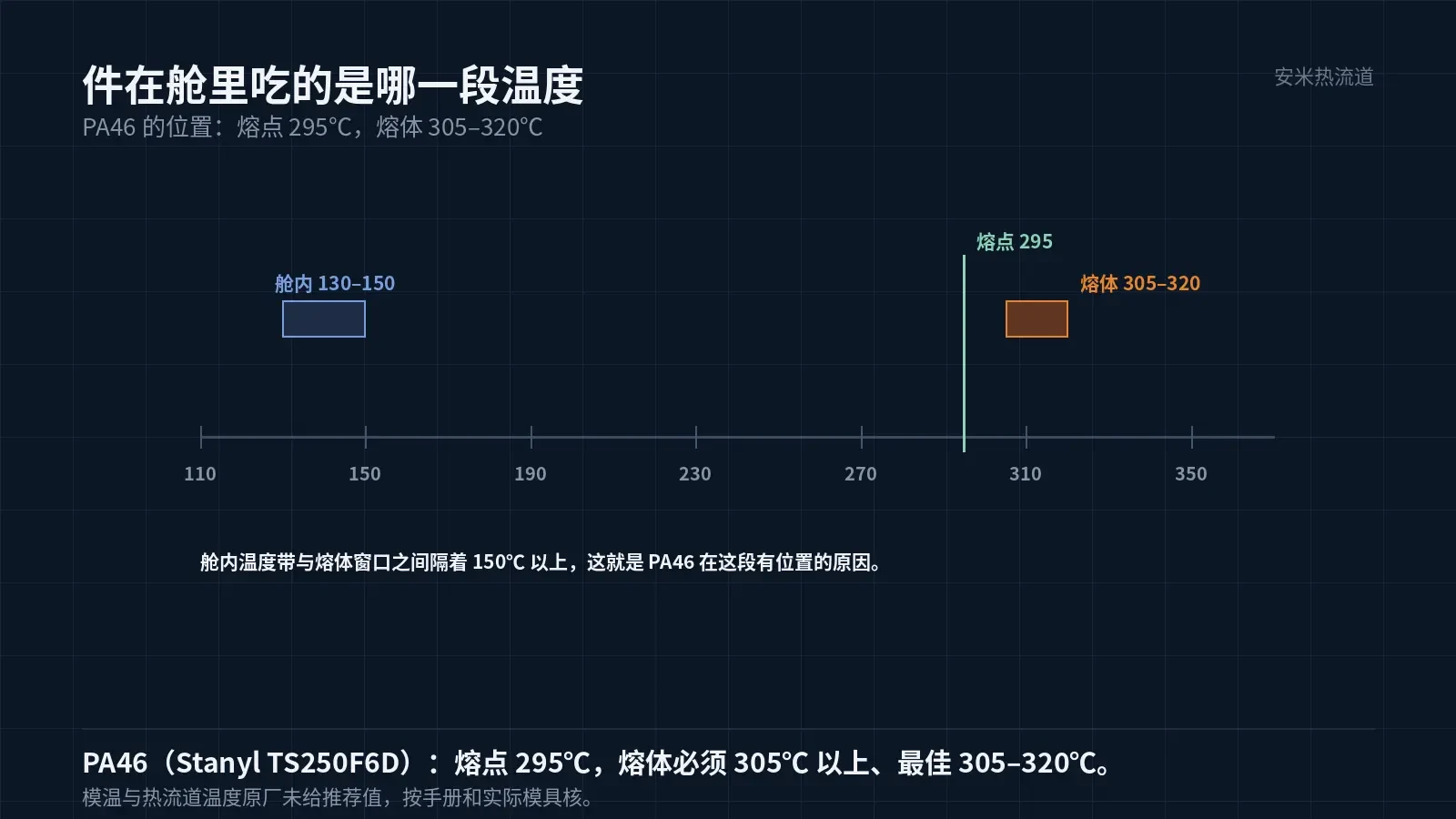
PA46 melts at 295°C, higher than PA66 but slightly lower than PA9T's 300°C. This makes it ideal for applications requiring long-term exposure to ~130°C and short-term peaks of 150°C, rather than environments exceeding 200°C.
Match the location and temperature before discussing materials. If the location is off by one segment, even more expensive materials won't solve the problem; if the location matches but the material isn't changed, issues will manifest differently—embrittlement, cracking, or dimensional drift.
To determine a part's segment, evaluate two factors: aging traces on failed components and their location within the bay. Embrittlement, powder shedding, and flat fracture surfaces indicate long-term overheating; yellowing, deformation, and localized softening signal short-term thermal shock. These failure modes require distinct treatments and must not be conflated.
Record location, ambient temperature, part geometry/wall thickness, and failure mode in a single table. Comparing two batches of parts from the same vehicle at the same location instantly reveals whether the material was changed and if the change was correct.
Melt Temperature Must Exceed 305°C
For grades like Stanyl TS250F6D (30% glass fiber), official melt processing conditions require: minimum temperature 305°C, optimal range 305–320°C, with both barrel and nozzle set to 305–320°C.
"Must be above 305" indicates a minimum threshold, not a suggestion. Temperatures below this level result in high melt viscosity and inadequate glass fiber dispersion, leading to short shots in thin-wall and long-flow regions.
The upper limit of 320°C is also critical. PA46 degrades if the melt remains at high temperatures for too long, causing darkening and reduced mechanical properties; therefore, residence time must be minimized even when using higher temperatures.
No OEM-recommended hot runner temperature values are provided. Verify settings against material datasheets and actual machine conditions; do not use data from PA9T or PPS.
Gate: SD Series Only
AM Industry product profiles recommend SD Series open hot tips only for PA4T, PA6T, PA9T, PA10T, PA46, and PPS. TP, VG, and PVG Series are not recommended.
PA46 exhibits low melt strength and rapid crystallization. The gate material often semi-solidifies before the valve pin completes mechanical shearing, causing cutting to become tearing. Tearing-induced gate marks are difficult to repair, particularly on cosmetic surfaces of automotive parts near the gate.
The SD Series uses hot tip insulation and rapid gate cooling for break-off. Fast-crystallizing materials perform well with this approach, thanks to quick solidification and clean separation.
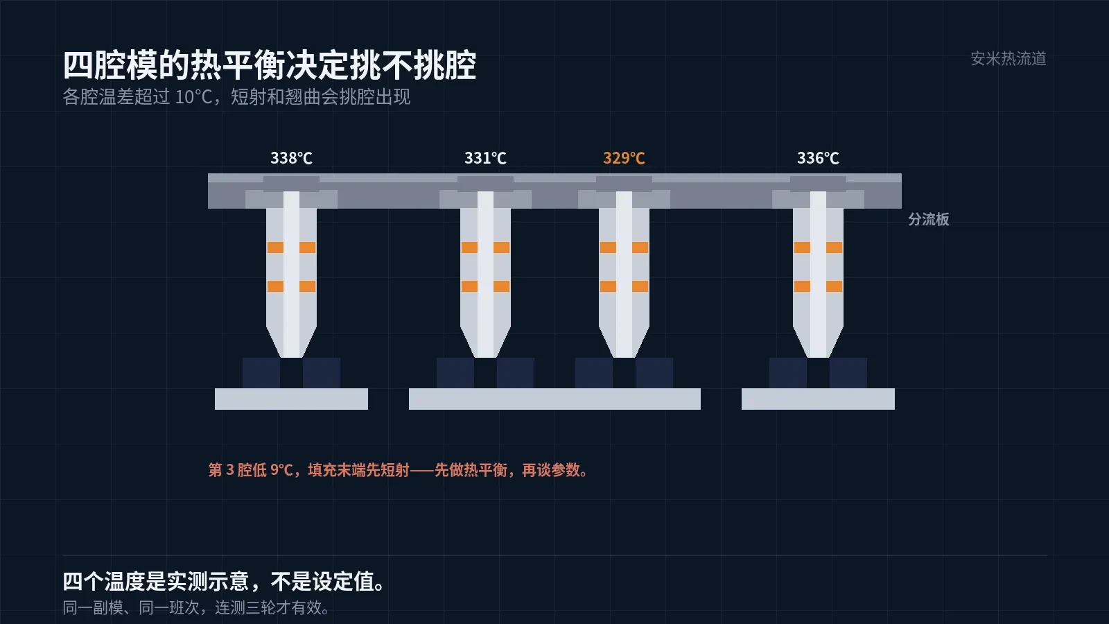
Thermal balance is critical in multi-cavity molds. Automotive connectors typically use 4 or 8 cavities; a temperature difference exceeding 10°C can cause selective short shots and warpage. Ensure thermal balance before optimizing parameters.
Two Shrinkage Directions
TS250F6D shrinkage is 0.4% in the flow direction and 1.1% in the transverse direction—a nearly threefold difference. This anisotropy stems from glass fiber orientation and cannot be eliminated through process adjustments.
Align part design with this differential: orient the long side along the flow direction and the short side perpendicular to it. Changing the gate position alters orientation, requiring recalculation of the dimensional chain.
The manufacturer does not specify recommended mold temperatures. You must verify the temperature against your tooling's actual conditions, as mold temperature directly affects crystallinity and final shrinkage. Using a mold temperature curve from another project will cause dimensional mismatches.
Three Critical Checks for Trial Molding
First, check for short shots. Inspect thin walls and areas far from the gate first; the 305°C lower limit is set specifically to address this.
Second, verify gate marks. The SD Series leaves a small bump; its position and size must be defined during the design phase. During trial molding, only check for stringing or skin formation.
Third, verify dimensions. Measure once for the initial shot, once after stabilization, and once after 24 hours. As PA46 crystallization progresses, the measurement taken after 24 hours will be closer to the final state.
Perform these three checks in sequence. Do not measure dimensions while adjusting parameters, as changing parameters invalidates the previous data set.
Drying and Material Changeover
PA46 absorbs more moisture than PA9T and requires thorough drying. Monitor hopper temperature, dew point, and residence time together; checking only temperature without the dew point is equivalent to no drying.
Thoroughly purge old material during changeovers. The processing temperature difference between PA46 and PA66 can cause unmelted particles from mixed materials, resulting in bright spots or pits on the product.
Provide part geometry, wall thickness, number of cavities, customer-specified temperature requirements, and current gate type. We will validate the solution against the PA46 processing window before providing a quote.
MATCHED BY MATERIAL AND DEFECT
This article covers stringing, drooling, clogging, and high-heat resins; refer to SD for gate freeze and break-off.
Register for a selection review and quote
Submit part, mold, and material details. Our engineers will evaluate the gate solution per part and provide a quote.
Upload a 2D layout drawing using the form.
Online selection and quote
Scan to register