
PV Connectors: Why PA9T Withstands 25-Year Outdoor Exposure
Material Applications15 min read
On this page
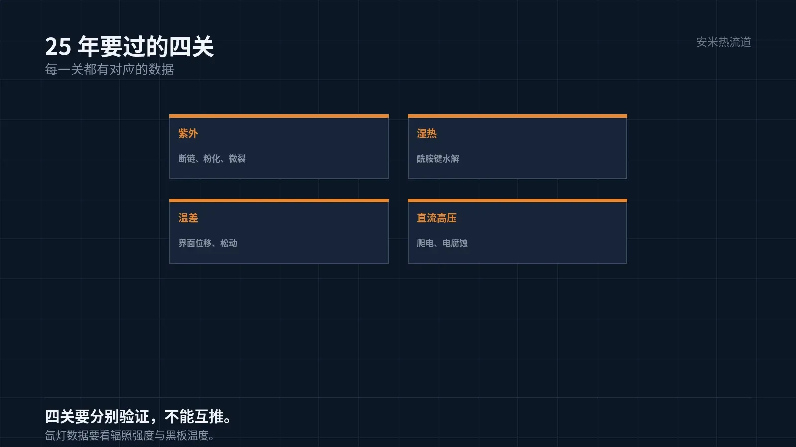
PV modules come with a 25-year warranty. Connectors are exposed to UV radiation and temperature fluctuations on rooftops, in the Gobi Desert, and coastal areas for the full 25 years.
Incorrect material selection causes cracking by year five. This article outlines the challenges faced during these 25 years.
Challenge 1: UV Resistance
UV damage to plastics causes chain scission. The surface first turns chalky and rough, then develops micro-cracks, and finally fractures.
Outdoor materials require UV stabilizers or inherent weather resistance. PA grades achieve weather resistance through modification, not intrinsic properties.
The aromatic ring structure of PA9T provides better UV resistance than PA66. However, "better" does not mean "maintenance-free"; the stabilization system still depends on the specific grade.
Therefore, material selection for PV components should be based on "outdoor aging data," not just claims of "good weather resistance."
Data typically includes strength retention and color change after specified hours of xenon lamp aging. Request this data from suppliers.
When reviewing data, verify the conditions. Results are not comparable if irradiance intensity, black panel temperature, or spray cycles differ; specify these conditions when citing data.
In the PV industry, it's common to calculate dosage based on the module's warranty period. Methods vary; confirm the standard with customers before quoting.
Another factor is reverse voltage. When a panel in a string becomes shaded, it enters reverse bias, exposing the connector to an electric field that differs from normal operating conditions.
Therefore, connector withstand voltage tests must include reverse bias conditions; testing only under forward bias fails to capture actual failure modes.
Shading also triggers bypass diode conduction. Heat generated by the diodes transfers to the connector, creating another underestimated failure path.
Therefore, connectors must be evaluated alongside their mounting locations. Connectors mounted behind the module backplane dissipate heat significantly worse than those on the frame.
Second Challenge: Damp Heat
Rooftop temperatures cycle daily. Daytime highs exceed 70°C, dropping below 20°C at night with dew formation.
Damp heat degrades polyamides via hydrolysis. Water and heat break amide bonds, causing strength to decline annually.
PA9T has a water absorption rate of 0.19% (ISO 62), which is one order of magnitude lower than PA66. Lower water absorption reduces the amount of raw material available for hydrolysis.
This is the main reason for using PA9T in photovoltaic applications: not higher temperature resistance, but lower water absorption.
Therefore, the answer to "why not use PA66" is clear: under 25 years of humid heat, PA66 degrades too rapidly in strength.
Third Challenge: Temperature Differential and Thermal Expansion
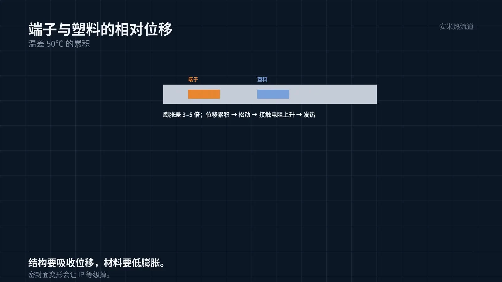
Connectors feature metal terminals. The coefficient of thermal expansion (CTE) mismatch between plastic and metal is 3–5 times.
A day-night temperature difference of 50°C causes relative displacement at the interface. Repeated cumulative displacement leads to loosening between the terminal and the plastic.
Loosening increases contact resistance. Higher resistance generates more heat, creating a positive feedback loop that ultimately leads to burnout.
Therefore, photovoltaic connector design must enable "displacement without loosening," typically achieved by absorbing movement via elastic structures.
For materials, choose those with low linear expansion coefficients. The aromatic structure of PA9T gives it a lower CTE than PA66.
Stage 4: Voltage and Creepage
PV string voltage can reach 100V or 1500V.. Failure mechanisms under high DC voltage include tracking and electrical erosion.
Insulation reliability depends on creepage distance and material tracking resistance. Specific ratings are verified against customer standards.
Outdoor contamination (dust, salt spray) reduces surface insulation. Therefore, enclosures must be sealed; IP68 is a common requirement.
Sealing performance depends on structure and material dimensional stability. Materials with high water absorption cause sealing face deformation, reducing the protection rating.
This links "material" and "structure": if the material is unstable, even good structural design will fail.
Molding Key Points
Drying: 70–90°C for 4–8 hours, moisture ≤0.20%. Outdoor components are sensitive to hydrolysis; thorough drying is required.
Barrel temperatures: 280–320/285–330/290–340°C; nozzle: 300–350°C. Use mid-range values to balance flow and degradation.
The manufacturer did not specify the mold temperature. For outdoor parts, use higher temperatures to ensure adequate crystallization, which improves dimensional stability and weatherability.
For gate diameters specified by AM Industry, only the SD Series is recommended. TP/VG/PVG are not suitable for PA9T.
G1350A is a 35% glass-filled grade with tensile strength of 200 MPa, flexural strength of 285 MPa, and flexural modulus of 10 GPa.
Validation and Failure Modes
Validation tests include UV aging, damp heat aging, temperature cycling, pressure resistance, insulation, IP rating, and mating force.
UV aging is measured in hours and typically requires doses equivalent to several years of outdoor exposure. Acceleration factors must be clearly stated.
Damp heat aging is performed at 85°C/85% RH for hundreds to thousands of hours. This is a standard condition in the photovoltaic industry.
Three failure modes: housing cracking (UV + stress), increased contact resistance (looseness), and insulation failure (moisture absorption + contamination).
Among these, increased contact resistance is the most subtle. It shows no visible defects and is only detected when power output drops.
Please provide voltage ratings, protection requirements, UV dosage, terminal structure, and current materials. We will review material and gate compatibility before providing a quote.
MATCHED BY MATERIAL AND DEFECT
This article covers stringing, drooling, clogging, and high-heat resins; refer to SD for gate freeze and break-off.
Register for a selection review and quote
Submit part, mold, and material details. Our engineers will evaluate the gate solution per part and provide a quote.
Upload a 2D layout drawing using the form.
Online selection and quote
Scan to register