
Why Use LCP for Thin-Walled OBC Skeletons?
Material Applications16 min read
On this page
Power modules for onboard chargers and inverters feature thin-wall frames and locating components with wall thicknesses of approximately 0.5 mm.
These components must withstand reflow soldering, high temperatures, and maintain flatness. LCP is a common solution that meets all three requirements.
Thin Walls and High Flowability
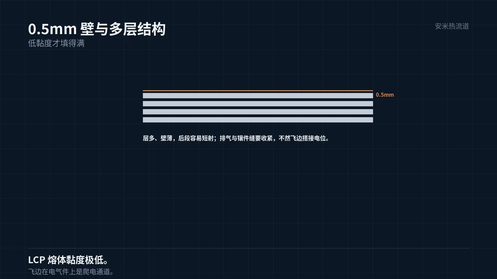
The power module frame has a wall thickness of approximately 0.5 mm and requires multi-layer structures within a confined space.
LCP has low melt viscosity, making it one of the few materials capable of forming multi-layer structures on 0.5 mm walls.
Low viscosity requires tighter mold venting and insert fits; otherwise, the melt may penetrate gaps and cause flash.
Flash on electrical components can create a risk by bridging two potentials and forming creepage paths.
Therefore, flash control in molds for thin-wall LCP parts is a critical quality parameter, not just an aesthetic concern.
Reflow Soldering
The power module assembly requires reflow soldering with a peak temperature of 240–260°C. The carrier must not deform or blister during oven processing.
LCP melts at 335°C, offering sufficient margin above the 260°C peak temperature. This ensures reflow compatibility.
Extremely low moisture absorption is the second criterion. Materials with high moisture absorption release water vapor during reflow, leading to blistering.
Therefore, LCP reflow capability depends on both heat resistance and low moisture absorption.
Note that pre-reflow drying is still required. Although LCP absorbs little moisture, surface-adsorbed water can cause surface defects.
Flatness and Low Warpage
Carrier flatness directly impacts chip mounting. A deviation of 0.05mm can cause poor solder joints.
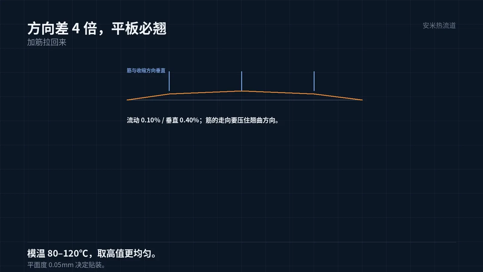
LCP exhibits low shrinkage but high directional variation: grades with 30% glass fiber show 0.10% flow-direction and 0.40% transverse-direction shrinkage—a 4x difference.
Large directional differences make flat areas prone to warping. Control strategies involve coordinating gate location and part geometry to absorb directional shrinkage within the structure.
A common practice is to add ribs along the warping direction. These ribs run perpendicular to the shrinkage direction to counteract deformation.
Mold temperature: 80–120°C. Use the higher value for more uniform shrinkage. Lower temperatures increase directional variation and warpage.
High-Frequency and Electrical Properties
Automotive electronic controls use high-frequency switches; the housing's dielectric properties impact parasitic parameters.
LCP offers a low dielectric constant and loss tangent among engineering plastics, with minimal moisture absorption and humidity sensitivity.
This factor is critical for high-voltage platforms (800V). Higher voltages increase the risks of creepage and partial discharge.
Therefore, housing materials must meet: thin-wall fillability, reflow stability, flatness, and dielectric stability.
The first three criteria depend on process and mold design; the fourth relies on material properties. LCP is one of the few materials that meet all four.
Another factor is weight. Automotive components are highly weight-sensitive; LCP's low density and thin-wall designs significantly reduce weight.
Reducing vehicle weight improves overall energy efficiency. This is a key design goal for new energy vehicles.
Thin walls also limit rigidity. The skeleton must support the chip and busbar; excessive thinness leads to deformation. Therefore, wall thickness balances fillability and rigidity.
Busbar mounting points concentrate stress. Bolt preload transfers through the busbar to the skeleton, making thin-walled areas prone to cracking.
Therefore, the skeleton requires thickening or metal bushings at bolt locations. Thickening consumes space, while bushings add process steps; both involve trade-offs.
Specify bolt torque for plastic parts. Do not apply metal part torque conventions directly, as they may cause crushing or insufficient preload.
Torque and preload must be calculated using thread and material friction coefficients, not determined by feel.
Torque control fixtures require regular calibration. Insufficient calibration causes torque variation during mass production, leading to individual failures.
Assembly process stability ultimately affects component failure rates. This aspect is often overlooked during the design phase.
Molding Key Points
LCP Hot Runner Temperature: 335–345°C. This narrow range demands precise control; low temperatures cause solidification, while high temperatures lead to degradation.
Mold temperature: 80–120°C. Use mid-to-high settings. Low mold temperatures increase orientation, worsening directional variation and warpage.
Gate dimensions follow AM industry standards. For LCP, use the SD/VG/PVG series; the TP series is not recommended. The SD series is commonly used for thin-wall parts.
High injection speed is required. Low-speed filling causes short shots on 0.5 mm walls, especially in the latter stages of multi-layer structures.
Maintain moderate holding pressure. In thin-wall parts, premature gate freezing blocks pressure transmission; resolve by adjusting injection speed and gate size.
Validation and Failure Modes
Validation covers dimensions and flatness (including post-reflow), reflow resistance (two cycles), dielectric properties, withstand voltage, flash resistance, and warpage.
Two reflow cycles are required. Double-sided boards must have substrates that withstand two thermal shocks.
Three failure modes: warpage (directional variation), blistering (moisture-related), and flash overlap (mold gaps).
Among these, flashover is the most subtle. It is invisible externally but causes failure during withstand voltage testing.
Therefore, for LCP electrical component acceptance, list "flash" as a separate item and inspect between critical potentials using a magnifying glass.
Please provide the wall thickness, number of layers, reflow profile, flatness, and voltage platform. We will verify based on material and gate type, then issue a quotation upon confirmation.
MATCHED BY MATERIAL AND DEFECT
This article covers stringing, drooling, clogging, and high-heat resins; refer to SD for gate freeze and break-off.
Register for a selection review and quote
Submit part, mold, and material details. Our engineers will evaluate the gate solution per part and provide a quote.
Upload a 2D layout drawing using the form.
Online selection and quote
Scan to register