
PEEK for Hydrogen System and Flow Battery Pumps/Valves
Material Applications17 min read
On this page
Hydrogen systems are sensitive to contamination, and flow batteries tend to precipitate. These constraints significantly narrow the material selection scope.
PEEK's advantage lies not in strength, but in its "cleanliness" and "wear resistance."
Hydrogen System Cleanliness Requirements
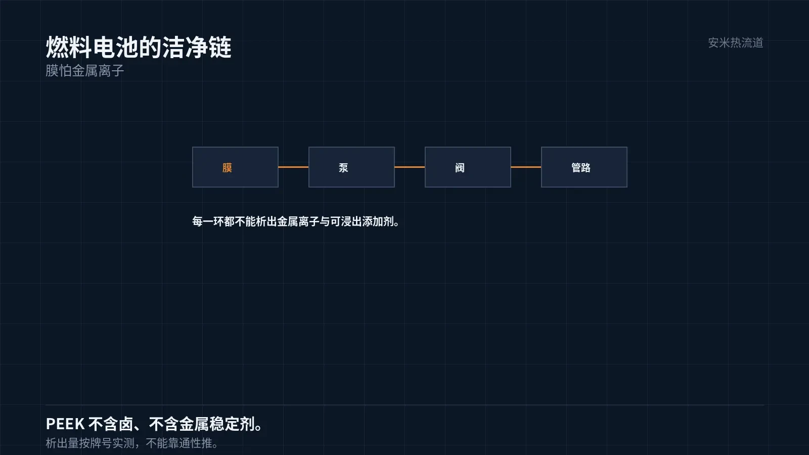
Proton exchange membranes in fuel cells are highly sensitive to metal ions. Even trace amounts degrade membrane performance and shorten service life.
Therefore, plastic components in hydrogen systems must not leach metal ions or contain extractable additives.
PEEK contains no halogens or metal stabilizers, minimizing leaching risk. This is the primary reason for its use in hydrogen systems.
However, "low leaching" must be verified. Soak samples in deionized water or simulated media, then measure ion content and total organic carbon (TOC).
This cannot be determined from general material properties. Additive systems vary by grade, resulting in different leaching levels.
Chemical Resistance for Flow Batteries
The electrolyte in flow batteries is either a strong acid (vanadium-based) or an organic system. Pumps and valves are permanently immersed in it.
Strong acids corrode most engineering plastics. PEEK offers excellent acid resistance and is one of the few materials suitable for long-term immersion.
Validate immersion using the actual medium, temperature, and duration by measuring weight, dimensions, and strength.
Permeation is another factor. In thin-walled parts subjected to long-term immersion, the medium permeates through the wall; this is especially critical for seals.
Therefore, pump and valve components for flow batteries often require combined "immersion + permeation" validation.
Permeation is measured by analyzing concentration changes after the medium passes through the thin wall or by monitoring pressure differential decay across both sides. Each method has specific applications.
Thin-walled components are at a disadvantage here. Thinner walls increase permeation rates, so seal thickness in flow batteries must incorporate safety margins.
Seal thickness cannot be arbitrarily reduced. Weight reduction and anti-permeation are directly conflicting requirements for these components.
Solutions include a "thin-wall + barrier layer" structure or adding metal liners to sealing surfaces. Both approaches increase processing steps and cost.
Another factor is medium temperature. Higher temperatures accelerate permeation; at the same wall thickness, permeation at 80°C is significantly higher than at 40°C.
Therefore, permeation verification must be based on the maximum operating temperature, not the average. Results calculated using average temperature are overly optimistic.
Permeation is also pressure-dependent. A greater pressure differential accelerates permeation; this effect is far more pronounced in high-pressure pump valves than in atmospheric components.
Therefore, pump valve seal designs must be validated against combined temperature and pressure conditions, not just single-condition test results.
Wear Resistance: Pump Shafts and Bearings
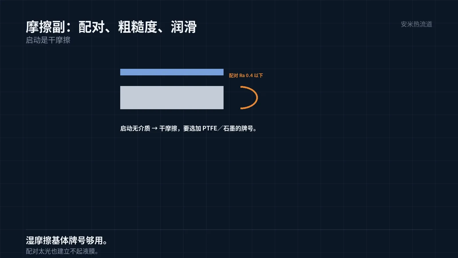
Pump shafts and bearings form a friction pair. In acidic or aqueous media with poor lubrication, wear occurs rapidly.
PEEK grades reinforced with carbon fiber or glass fiber provide high compressive strength and low friction coefficients, making them ideal for bearings and thrust washers.
Control the surface roughness of mating parts. Wear decreases significantly below Ra 0.4, but surfaces that are too smooth fail to form a liquid film.
For dry friction applications, select grades with lubricants (PTFE, graphite). For wet friction applications, standard base material grades are sufficient.
This criterion depends on the pump's startup conditions: dry friction occurs when starting without medium.
Processing: High-Temperature Thresholds
PEEK grade 650G: Rear zone 375°C, middle zone 380–385°C, front zone 390°C, nozzle 395°C; mold temperature 170–200°C.
Barrel heating capacity must exceed 400°C. The equipment is the primary barrier; standard machines cannot process this material.
Dry at 120–150°C for 3–5 hours. Hydrogen systems are sensitive to moisture and contamination; retain drying records.
For molds with a 200°C temperature, use high-temperature oil in the cooling channels. Water temperature is insufficient to reach the required mold temperature, which results in incomplete crystallization.
Gate dimensions adhere to AM industry standards. For PEEK, the SD, VG, and PVG series are suitable; the TP series is not recommended. The VG series is commonly used for precision parts.
Dimensions and Fits
Pump valve fit clearances are tight. Typically, 0.02–0.05mm. PEEK grade 450GL30 exhibits shrinkage of 0.30%/0, with a threefold directional variation.
Directional shrinkage varies by a factor of 3; block parts are harder to control, while ring and long-strip parts are easier. Part geometry must align with the material.
Mold temperature uniformity directly determines dimensional consistency. Cooling channels must be zoned with independent temperature control for each zone.
Another factor is post-shrinkage. Due to its high crystallinity, PEEK exhibits slight shrinkage after ejection; dimensions should be measured only after stabilization.
Therefore, the dimensions of precision PEEK parts are typically measured 24 hours after ejection, not immediately.
Validation and Failure Modes
Validation includes media immersion, extractables, wear resistance (bench test), dimensions, pressure resistance, permeation, and cleanliness.
Extractables testing adheres to customer cleanliness standards; hydrogen system requirements are typically stricter than general industrial standards.
Three failure modes exist: excessive extractables (additives or degradation products), excessive wear (mating surfaces or lubrication), and dimensional drift (post-shrinkage).
Among these, extractables are the most difficult to trace. They do not appear as part failures but as system performance degradation, making root cause analysis challenging.
Once the material grade is finalized, avoid changing it. Changing the grade alters the extractables profile and requires full re-validation.
Please provide the medium, temperature, pressure, cleanliness requirements, fit clearance, and current material. We will verify these against operating conditions and structure before providing a quote.
MATCHED BY MATERIAL AND DEFECT
This article covers stringing, drooling, clogging, and high-heat resins; refer to SD for gate freeze and break-off.
Register for a selection review and quote
Submit part, mold, and material details. Our engineers will evaluate the gate solution per part and provide a quote.
Upload a 2D layout drawing using the form.
Online selection and quote
Scan to register