
ESS Battery Module Insulators: Why Electrolyte Resistance Matters
Material Applications17 min read
On this page
Insulation components in battery modules do not contact electrolyte under normal conditions but must withstand it if cell leakage occurs.
This "worst-case" scenario drives material selection: choose based on failure conditions, not normal operating conditions.
Failure Conditions as Design Inputs
Energy storage module insulation components include separators, brackets, and covers. Under normal operation, they only experience temperature fluctuations and vibration.
Cell leakage is rare, but if it happens, electrolyte can flow onto insulation components. Electrolyte is highly corrosive.
If corrosion breaches the insulation, the positive and negative electrodes short-circuit, triggering thermal runaway. Design verification must therefore confirm insulation integrity after leakage occurs.
This requirement significantly elevates material standards: standard engineering plastics cannot withstand prolonged electrolyte immersion.
PPS offers excellent chemical resistance to electrolytes and common solvents, making it ideal for energy storage applications.
Chemical resistance varies with temperature. Resistance at room temperature does not ensure performance at 60°C; performance at 60°C does not guarantee it at 80°C. Verify compatibility at the module's actual operating temperature.
Consequently, insulation material solutions are typically defined jointly with cell manufacturers. Different cell chemistries use different electrolytes and thus require different solutions.
The module's exhaust design must also be considered. Components in the exhaust path during thermal runaway must withstand short-term exposure to high-temperature smoke; standard insulation components cannot.
Components in the exhaust path typically require separate material selection or structural thermal insulation. This is a system-level design issue that cannot be solved by individual parts alone.
Therefore, material selection for energy storage components falls into two categories: standard insulation components and thermal runaway path components. The validation requirements for these two categories differ entirely.
Quotations must list the two categories separately. Quoting them at a single price will result in losses on thermal runaway path components.
Molds for standard and path components differ. Path components often require added insulation or increased thickness, necessitating a redesign of the mold structure.
Clarify this early in the project. Discovering mid-project that two categories are required will lead to mold rework and schedule collapse.

Flame Retardancy: Beyond V-0
Energy storage components must meet high flame-retardancy standards. In addition to V-0, glow wire tests and dripping behavior during combustion must also be evaluated.
Drooling is a hazard. Molten material dripping during combustion can ignite components or cells below.
PPS contains sulfur, providing excellent flame retardancy; it typically meets high fire safety ratings without added flame retardants. It is halogen-free, resulting in low corrosivity of combustion smoke.
Specific grades and test methods are validated against customer standards; no codes or values are provided. This is especially critical in the energy storage industry, where standards vary by manufacturer.
Therefore, the claim "PPS has good flame retardancy" must specify the standard and grade; otherwise, it is meaningless.
150°C Mold Temperature and Dimensions
PPS mold temperature must exceed 130°C, typically 150°C. Low mold temperature causes incomplete crystallization, resulting in poor toughness and surface quality.
DURAFIDE 1140A1 reinforced with 40% glass fiber exhibits shrinkage of 0.3% to 0.8%, with a directional difference factor of 2.7. On insulating parts, hole positions should align with the flow direction.
Mold temperature uniformity matters more than the absolute value. A 5°C variation causes hole position shifts and tightens module assembly.
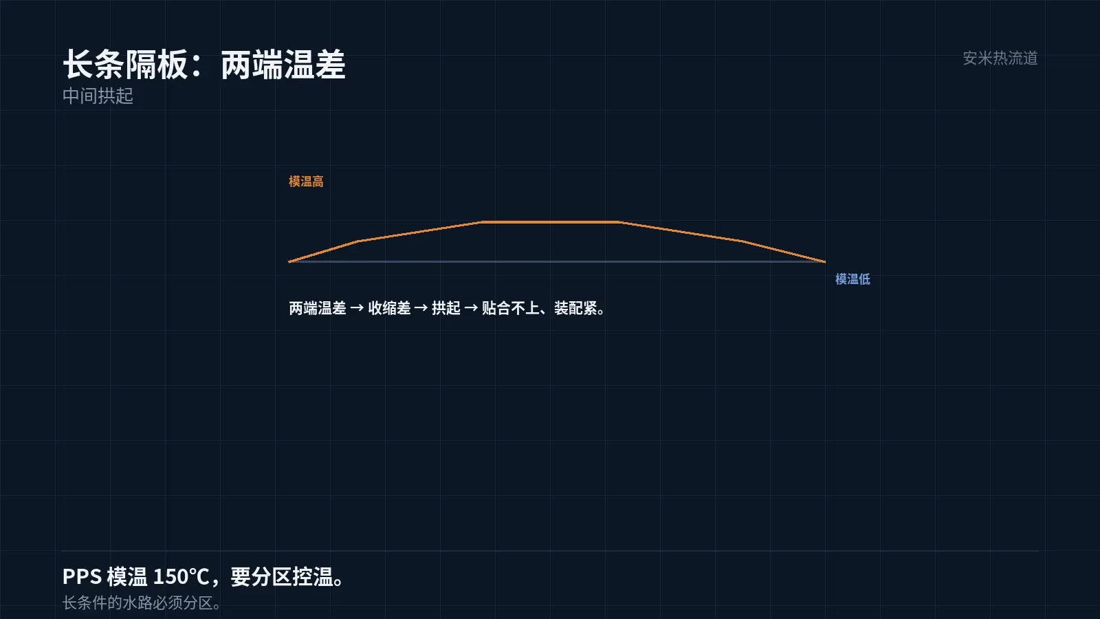
Thus, molds for energy storage components require zoned water channels with independent temperature control per zone. This is especially critical for elongated separators.
Temperature differences are most pronounced at both ends of long conditions. Excessive end-to-end temperature variations cause central warping, preventing proper separator fit.
Electrolyte Resistance Verification
Verification involves immersing parts in an electrolyte under actual temperature and time conditions. Common conditions are 60°C for several hundred hours.
Three parameters are measured after immersion: weight change, dimensional change, and mechanical strength. Resistance is confirmed only if all three fall within the specified ranges.
Another parameter is insulation resistance after immersion, which directly impacts safety under failure conditions.
Electrolyte formulations vary by cell manufacturer; verify using the customer's actual electrolyte, not a generic formulation.
This is a common pitfall: using data from Manufacturer A for Manufacturer B's project often causes verification to fail.
Molding Key Points
Pre-dry at 140°C for 3 hours or 120°C for 5 hours. Although PPS has low moisture absorption, drying is required for cosmetic and insulating parts.
Nozzle temperature: 310–320°C; melt temperature must not exceed 360°C. Overheating causes degradation and reduces insulation performance.
Venting groove depth: 0.005–0.008 mm. PPS has low viscosity; excessive depth causes flash, which can initiate creepage on insulating parts.
Pin-point gates typically use φ0.8–1.2 mm. Use smaller values for thin-walled insulating parts, but avoid going too small to prevent short shots.
Use SD Series hot runners. PPS maintains consistent residence viscosity, making it suitable for continuous production; however, stable viscosity does not guarantee absence of degradation.
Failure Modes and Acceptance Criteria
Three failure modes: insulation breakdown (due to contamination or moisture absorption), mechanical failure (warping or brittle fracture), and non-compliant flame retardancy (incorrect grade selection).
Among these, insulation breakdown is the most hazardous. It presents no visible signs and only appears during withstand voltage testing or actual operation.
Acceptance tests include: dielectric withstand, insulation resistance (including after immersion), flame retardancy, dimensions, warping, and vibration.
Cleanliness is also critical. Dust and oil on insulating surfaces significantly reduce withstand voltage ratings.
Specify cell type, electrolyte, voltage rating, flame retardant standard, and module structure. We will verify materials and gate design prior to providing a quote.
MATCHED BY MATERIAL AND DEFECT
This article covers stringing, drooling, clogging, and high-heat resins; refer to SD for gate freeze and break-off.
Register for a selection review and quote
Submit part, mold, and material details. Our engineers will evaluate the gate solution per part and provide a quote.
Upload a 2D layout drawing using the form.
Online selection and quote
Scan to register