
Why Is PPS a Safe Choice for Micro Connectors Requiring Reflow Soldering?
Material Applications16 min read
On this page
Consumer electronics connectors pass through SMT lines and reflow soldering. Furnace temperature testing ensures plastic parts do not deform, blister, or lose strength.
PPS is stable in this regard but lacks robustness. This article explores that trade-off.
Reflow Soldering Effects on Plastic Components
The reflow profile is defined by the customer, with varying peak temperatures, durations, and heating rates. Plastic parts must be validated against the customer's specific profile, not a generic one.
In the furnace, plastic components expand due to heat. Potential issues include dimensional changes, warping, blistering, and terminal displacement.
Blistering occurs due to moisture. At high temperatures, water trapped in the material vaporizes, generating internal pressure that forms bubbles. PPS exhibits low moisture absorption and outperforms nylon in this regard.
Warpage results from residual stress and anisotropy. With 40% glass-filled PPS, the shrinkage difference between the flow and transverse directions is significant, causing thin-walled parts to warp easily.
Terminal displacement is caused by thermal expansion. Because the plastic part and metal terminals have different coefficients of thermal expansion, terminal positions shift after reflow, impacting subsequent assembly.
Among these three issues, terminal displacement is the most difficult to correct. Since plastic thermal expansion cannot be altered, structural changes are required: adding compensation, modifying terminal fixation methods, or using floating terminals.
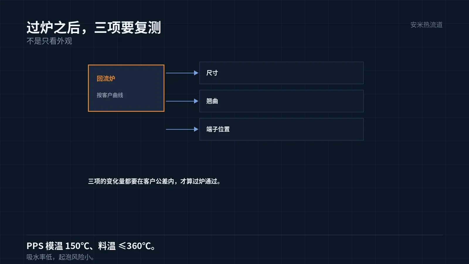
PPS strengths: thermal stability and dimensional accuracy
PPS mold temperature: 150°C. Melt temperature must not exceed 360°C. Nozzle temperature: 310–320°C. This profile ensures sufficient crystallization and thermal stability.
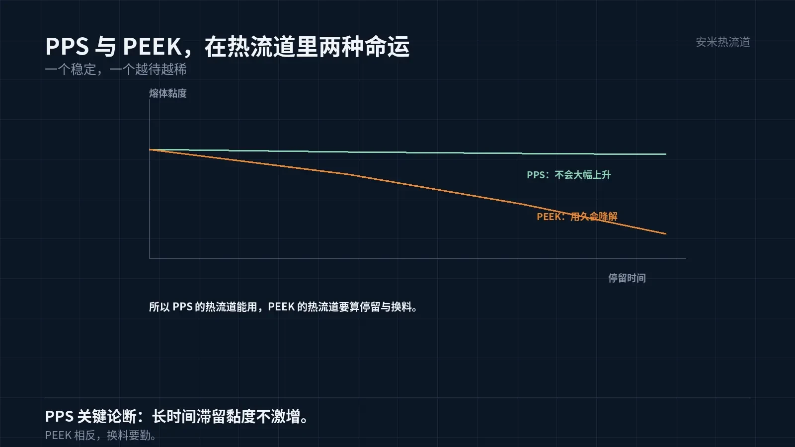
PPS Key Point: Viscosity remains stable during extended residence times. Manufacturer data supports the use of hot runners with PPS.
In contrast, PEEK degrades over time. These two materials exhibit opposite behaviors in hot runner systems; do not simply categorize them as high-temperature resins when selecting materials.
PPS shrinkage is 0.3%/0.8%. Anisotropy is lower than LCP but still present. For micro-parts with tight dimensional tolerances, this factor must be accounted for in mold flow analysis.
A mold temperature of 150°C aids thin-wall filling but raises the ejection temperature, necessitating careful design of parting lines and draft angles.
Another advantage of PPS for micro-parts is its low moisture absorption. Unlike nylon, it requires less stringent drying, which simplifies shop floor management and reduces the risk of blistering.
Recommended pre-drying: 140°C for 3 hours or 120°C for 5 hours. Micro-parts require small material volumes, so large-capacity dryers are unnecessary; however, temperature accuracy is critical.
Another prerequisite for zero deformation after reflow is low in-mold stress. High mold temperature, adequate holding pressure, and uniform cooling reduce residual stress and minimize post-reflow deformation.
PPS Comes at the Cost of Brittleness
PPS exhibits low elongation at break. Pins, thin walls, and snaps on micro parts are prone to fracture under lateral loads.
Fractures typically occur at pin roots and thin-wall corners. The former results from stress concentration; the latter from weld lines.
Address pin root issues through geometry: add fillets and transitions, and avoid sharp corners. These must be specified in the part drawing, as they cannot be modified after mold opening.
Another pin issue is length. Longer pins experience higher bending moments under load, increasing fracture risk. In micro parts, pin length is constrained by pitch, leaving minimal margin.
Address weld line issues through gate placement and venting: position gates to keep weld lines away from high-stress areas, and ensure effective venting to improve weld line strength.
Another approach is to increase the mold temperature. Higher temperatures enable sufficient molecular chain diffusion at weld lines, enhancing strength. PPS naturally requires high mold temperatures, providing an advantage in this regard.
However, high mold temperatures can also cause warpage and extend cycle times. Since micro part cycles are already short, even a slight temperature increase affects capacity. A total cost analysis is required.
Another way to address PPS brittleness is using modified grades. Adding elastomers or adjusting glass fiber content improves toughness, but reduces thermal and stiffness margins.
Switch to modified grades based on part stress analysis: use for impact-dominated parts; do not change for temperature-resistant parts.
Vent Grooves and Pin Gates
PPS vent groove depth is 0.005–0.008mm.. Micro-parts have small cavities; fewer vents are needed, but their positions must be precise.
Pin gates typically use φ0.8–1.2mm.. Micro-gates should be smaller, but excessive reduction increases shear; PPS is sensitive to shear.
Gate locations must be kept away from terminal areas. High flow velocity near the gate causes strong glass fiber alignment, leading to varying mechanical properties in this region.
Glass fiber orientation is especially pronounced in micro-parts. In 0.15mm-wall components, fibers align with the flow direction; strength perpendicular to the flow depends on the resin and is significantly weaker.
Therefore, micro-part strength design must account for anisotropy rather than isotropy. This applies to both PPS and LCP.
Obtain anisotropic data from the original manufacturer by grade. Different grades vary in glass fiber content and length, resulting in varying degrees of anisotropy.
Verification: Measure Before and After Reflow Soldering
Group 1 (pre-reflow): dimensions, terminal position, and appearance. Group 2 (post-reflow): the same three attributes to assess changes. Group 3: thermal cycling after reflow to evaluate cumulative effects.
Dimensional variation in micro parts is typically within 0.02mm.. This level of precision requires optical measurement; calipers cannot detect it.
Measurement datums must be consistent. Use the same datum, equipment, and method for pre- and post-reflow measurements; otherwise, data are not comparable.
Submit part drawings, terminal position tolerances, reflow profiles, and cavity counts. We will evaluate reflow deformation and gate solutions, then issue a quotation upon confirmation.
MATCHED BY MATERIAL AND DEFECT
This article covers stringing, drooling, clogging, and high-heat resins; refer to SD for gate freeze and break-off.
Register for a selection review and quote
Submit part, mold, and material details. Our engineers will evaluate the gate solution per part and provide a quote.
Upload a 2D layout drawing using the form.
Online selection and quote
Scan to register