
Why Use PA9T Instead of LCP for Micro Connector Housings?
Material Applications16 min read
On this page
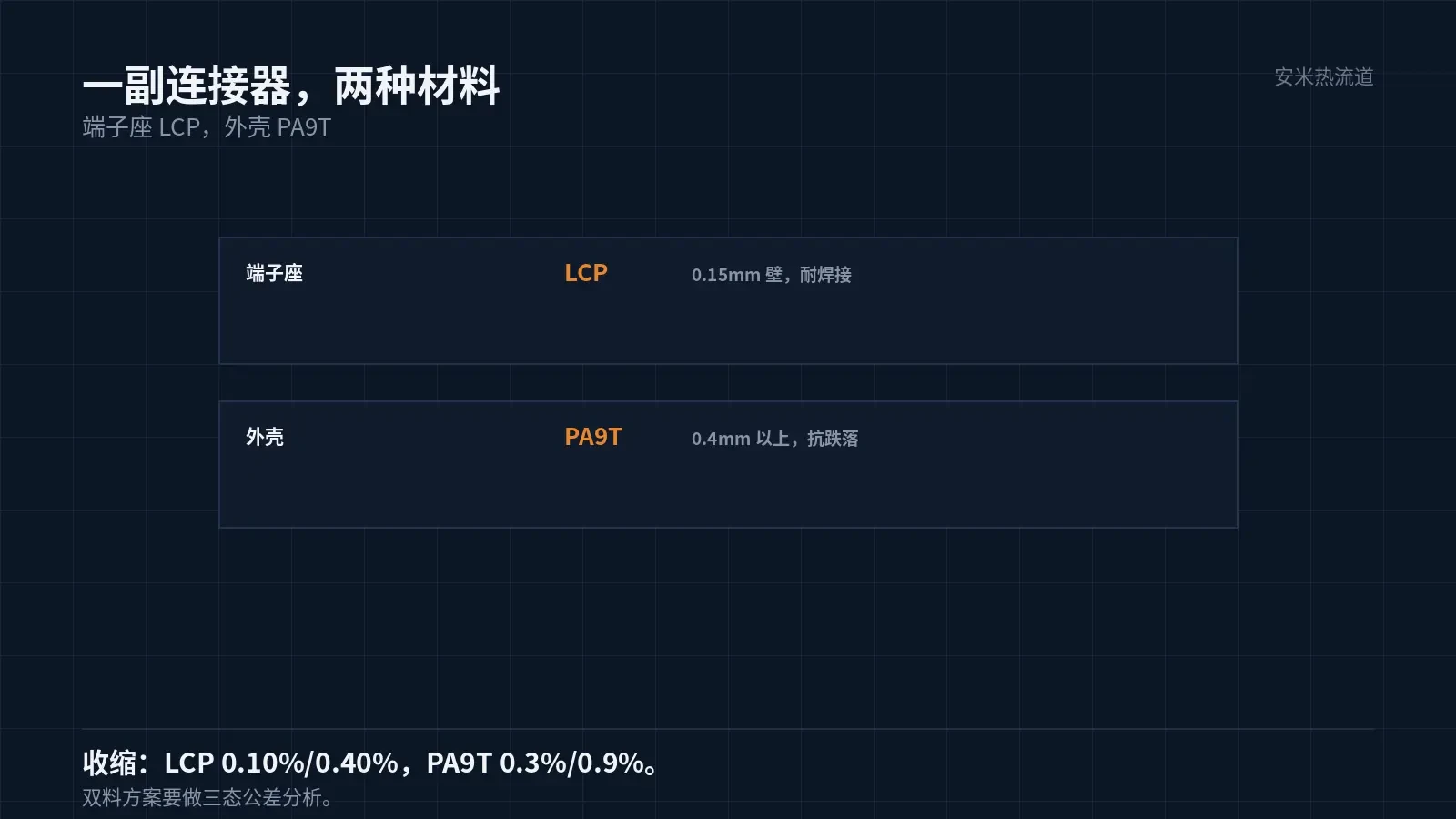
In the same connector, using LCP for the terminal block and PA9T for the housing is common in consumer electronics. The rationale varies by material.
The terminal block needs thin walls, stability, and solder resistance; the housing requires toughness, drop resistance, and aesthetics. This article covers the latter.
Housing failure occurs due to drops.
Drops are routine for smartphones, earphones, and watches. The connector housing withstands drop impacts, where LCP's brittleness is a weakness.
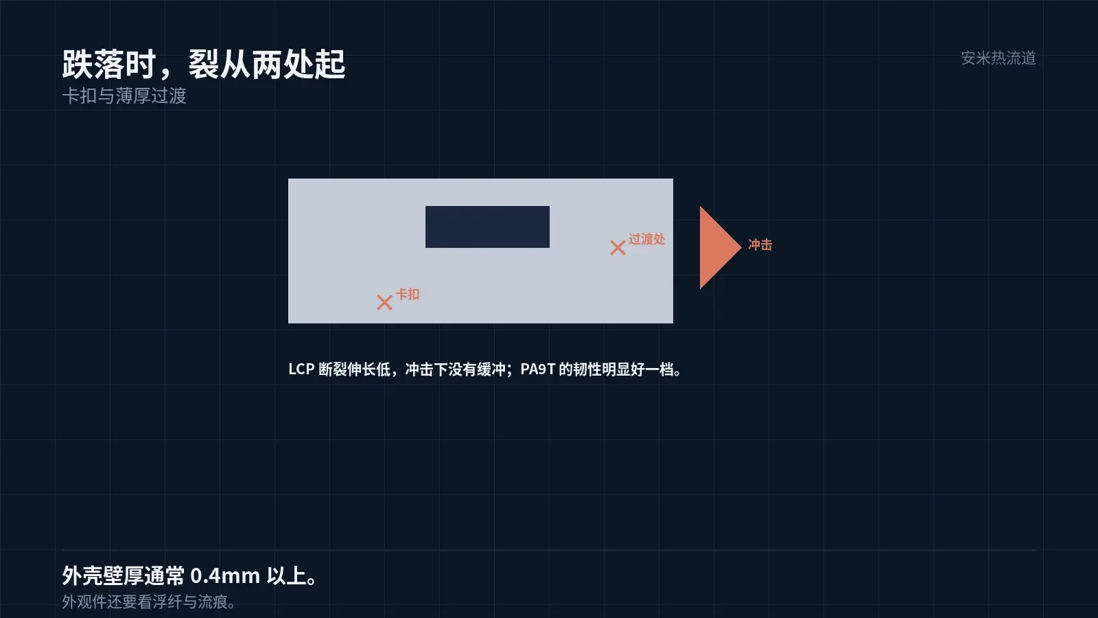
LCP exhibits low elongation at break and lacks impact cushioning, causing direct cracking. Cracks typically occur at snaps, corners, and transitions between thin and thick walls.
PA9T offers significantly better toughness than LCP, delivering superior impact resistance in identical structures. This is the primary reason for selecting PA9T for housings.
The second reason is appearance. LCP shows noticeable glass fiber bloom and a rough surface, whereas PA9T with glass fiber delivers superior surface quality, making it ideal for cosmetic components.
The third reason is assembly. PA9T snaps withstand multiple insertions and removals, while LCP snaps loosen after just two cycles, impacting repair and rework.
Cost is a key factor. LCP materials cost more and require more complex processing than PA9T; using PA9T for large-area parts like housings delivers significant savings.
PA9T cannot fill 0.15mm walls
PA9T has lower melt flowability than LCP. For the same thin wall, LCP fills it completely, while PA9T is prone to short shots.
Therefore, PA9T is used for housings with wall thicknesses typically above 0.4mm;. For terminal blocks with 0.15mm walls, LCP is still required.
This division of labor is driven by material capabilities, not design preference. Forcing PA9T into thin-wall applications compromises yield rates.
Flow length ratios must be calculated for thin walls. For PA9T on a 0.15mm wall, the flow length ratio is roughly half that of LCP; exceeding this limit causes short shots. This calculation is required during part drawing review.
To use PA9T in thin walls, increase the melt temperature and injection speed. However, with a maximum melt temperature of 340°C and shear rising due to higher injection speeds, there is limited room for adjustment on both fronts.
PA9T barrel temperatures are 280–320/285–330/290–340°C; nozzle temperature is 300–350°C. Use grade-specific data sheets only—do not copy settings from other nylons.
Dry at 70–90°C for 4–8 hours until moisture content is ≤0.20%. Although the water absorption rate of 0.19% appears low, cosmetic parts are sensitive to moisture marks that become visible if drying is insufficient.
Co-molding two materials: Interface issues
Some designs use two-color or two-shot molding to form the terminal block and housing in a single tool. The key challenge is ensuring reliable interface bonding.
The melting point difference between LCP and PA9T is 35°C, and the molding sequence affects the interface. Overmolding a high-temperature material first with a low-temperature material relies on mechanical interlocking at the interface.
Interface strength depends on surface roughness and temperature. If the first part's surface is too smooth, the second material cannot grip it; if the first part's temperature is too low, the second material quenches rapidly at the interface.
Two-shot molds are complex and expensive. Most projects still use separate molding followed by assembly for simplicity and reliability.
If two-shot molding is used, tolerance analysis is required: Shrinkage rates differ (LCP 0.10%/0.40%, PA9T 0.3%/0.9%), causing fit clearances to vary with temperature.
Tolerance analysis must be performed for three conditions: room-temperature assembly, high-temperature operation, and low-temperature storage. The design passes only if clearances remain within the specified range across all three conditions.
Clearance fits for micro-parts are typically 0.02–0.05mm.. At this scale, differential shrinkage between the two materials can lead to assembly failure.
Cosmetic part processing details
For glossy PA9T cosmetic parts, higher mold temperatures are required. Since the OEM does not specify recommended values, set parameters based on part geometry through trial and error.
Low mold temperature causes rapid melt cooling at the cavity surface, leading to flow marks and weld lines that fail appearance requirements. High mold temperature increases cycle time and requires careful part ejection.
Gate placement greatly impacts appearance. Install gates on non-visible surfaces or use submarine gates; if visible, gate marks must be treated.
Polishing, sandblasting, and painting enhance appearance but add cost. Designing the gate to be hidden is more cost-effective than post-processing.
Color consistency is also required for cosmetic parts. Color differences within and between batches must be controlled. Retain color samples when changing materials.
The mold polishing grade for cosmetic parts must be specified. Mirror polishing meets appearance standards but is costly; EDM texture is more affordable but may show flow marks. This item should be listed separately in the quotation.
Validation: Functional Testing Post-Drop Test
Group 1 Appearance: Color variation, flow lines, weld lines. Group 2 Assembly: Insertion/extraction cycles, snap-fit cycles. Group 3 Drop: Performed at customer-specified height and count; verify functionality after drop.
Among the three groups, Group 3 best highlights material selection issues. LCP housings frequently fail drop tests.
Another often-overlooked group is full-assembly drop testing after assembly. Individual parts may pass drop tests, but results can differ once assembled into the final unit due to changes in center of gravity and stress distribution.
Please provide the housing drawing, wall thickness, drop test requirements, and appearance grade. We'll review material allocation and dual-shot solutions before confirming pricing.
MATCHED BY MATERIAL AND DEFECT
This article covers stringing, drooling, clogging, and high-heat resins; refer to SD for gate freeze and break-off.
Register for a selection review and quote
Submit part, mold, and material details. Our engineers will evaluate the gate solution per part and provide a quote.
Upload a 2D layout drawing using the form.
Online selection and quote
Scan to register