
Black Spots in Micro Parts: Linked to Machine Runtime, Not Material
Material Applications17 min read
On this page
Micro connectors weigh less than 0.1 g, leading to small shot sizes. For such parts, the material residence time in the barrel and hot runner is significantly longer than the injection cycle time.
Therefore, black spots are typically caused by prolonged material residence time rather than contamination. This article explains why.
Calculating Residence Time
Residence time equals the total material volume in the barrel and runners divided by shot size. For micro parts, the small shot size (denominator) amplifies residence time.
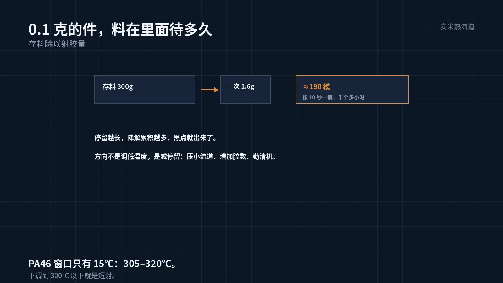
Example: With 300 g of material in the hot runner and barrel, a part weight of 0.1 g, 16 cavities, and a shot size of 1.6 g, the residence time is approximately 190 shots.
At a 10-second cycle time, 190 cycles exceed 30 minutes. During this period, the material stays at high temperature and accumulates degradation.
One sign of degradation is black spots: locally overheated or stagnant material carbonizes and gets carried into the part with the melt. This issue is especially prevalent in micro parts.
For black spots on micro parts, check residence time first, then material quality. Do not reverse this order.
Residence time can be calculated more precisely by separating the hold-up volume in each barrel section and the hot runner. The hot runner typically has the longest residence time due to its higher temperatures.
PA46 has a narrow processing window
PA46 melt temperature must exceed 305°C, with an optimal range of 305–320°C. The window is only 15°C.
A narrow processing window limits how much you can lower the melt temperature. Some sites reduce temperatures below 300°C to minimize black spots, which leads to short shots and weak weld lines.
Increasing the temperature is also not viable. Above 320°C, degradation occurs, resulting in more black spots—a common vicious cycle for micro parts.
The correct approach is not to adjust temperature, but to reduce residence time: minimize runner volume, reduce material retention, and shorten changeover cycles.
Another way to reduce residence time is to increase injection speed and shorten cycle time. Shorter cycles boost the number of molded parts per unit time, accelerating material turnover and reducing residence time.
Runner volume reduction depends on part geometry and cavity count. More cavities increase shot weight and reduce residence time; fewer cavities extend residence time. This must be calculated before tooling.
Therefore, the cavity count for micro parts is not just a capacity concern but also a process issue. Too few cavities make it difficult to control black spots.
Minimize the hot runner channel diameter. Larger diameters increase material retention and residence time. For micro parts, size the hot runner channel based on shot weight rather than standard component dimensions.
The nozzle tip diameter must also be small. A large tip retains more material, causing the melt at the nozzle front to update slowly and become a hotspot for black spots. The tip diameter must match the gate size.
Purge is required
Purge frequency should be based on residence time. For lines with a 30-minute residence time, purge hourly rather than per shift.
Select the correct purging compound. Using the wrong one leaves residues that contaminate the next batch, causing black spots. The compound's heat resistance must exceed PA46 processing temperatures.
Verify purge effectiveness: Run several cycles after purging to confirm black spots are gone. If they persist, dead zones exist in the flow channels and require disassembly for inspection.
Dead zones typically form at channel corners, hot runner nozzles, and the screw head within the barrel. Purging compounds cannot fully clean these areas; disassembly and inspection are required.
Set disassembly inspection intervals based on part sensitivity to black spots. Use shorter intervals for cosmetic and micro parts; longer intervals are acceptable for large or dark-colored parts.
Maintain a logbook instead of relying on experience. Record: last inspection date, number of black spots, and purging compound batch.
Also manage material changeover transitions. Switching between dark and light materials, or high-temperature and low-temperature materials, can cause black spots if the transition is incomplete. Perform multiple shots during the transition; do not skip this step.
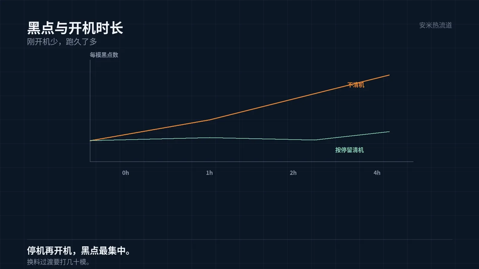
Black spots are most concentrated after shutdown and restart. During downtime, material remains static at high temperature, causing severe degradation. After restarting, run scrap shots until black spots disappear before starting production.
Drying: Do not overlook residence time.
PA46 absorbs moisture readily. Undried material releases steam above 305°C, leading to silver streaks on parts and localized melt degradation.
Silver streaks and black spots often occur together, leading to misdiagnosis. Silver streaks result from moisture; black spots are caused by carbonization. Corrective actions differ.
Follow the datasheet for drying temperature and time. Ensure dryer capacity matches production volume to avoid material waiting at the machine.
Manage material handling: drying storage duration, sealing methods, and transfer procedures. Leaving material exposed for hours negates the drying process.
Drying temperatures for PA46 differ from PA9T; refer to the respective datasheets. When producing both materials on the same line, configure separate drying parameters—do not share settings.
Verification: Black spot counting
Group 1 (Visual): Sample multiple parts per shot, count black spots, and classify by area. Group 2 (Mechanical): Strength in black spot areas is typically lower than in normal areas. Group 3 (Electrical): Black spots are conductive impurities; their impact is more severe on micro-parts with small insulation gaps.
Black spot counting requires defined standards: size threshold and allowable count per part. Align these criteria with the customer; do not set them independently.
Record black spot locations. Concentration near the gate indicates gate shearing; dispersion across the entire part suggests material issues; concentration at the end indicates venting problems. Location helps identify the cause.
Please provide the part weight, number of cavities, hot runner volume, black spot standards, and current purge cycle. We will verify based on residence time and purging, then submit a quotation upon confirmation.
MATCHED BY MATERIAL AND DEFECT
This article covers stringing, drooling, clogging, and high-heat resins; refer to SD for gate freeze and break-off.
Register for a selection review and quote
Submit part, mold, and material details. Our engineers will evaluate the gate solution per part and provide a quote.
Upload a 2D layout drawing using the form.
Online selection and quote
Scan to register