
How Thin Can LCP Go for 0.35mm Pitch Micro Connectors?
Material Applications16 min read
On this page
Board-to-board connectors in mobile phones feature a 0.35mm pitch and a wall thickness of 0.12–0.15mm between terminals. At this scale, material options are limited, with LCP being the primary choice.
However, "usable" does not mean "easy to manufacture." Micro-part yield rates depend on several specific factors. This article breaks them down.
Filling 0.15mm walls depends on speed, not pressure.
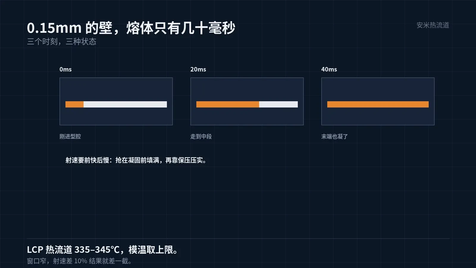
For 0.15mm walls, melt flow from the gate to the end takes only tens of milliseconds. During this time, the melt temperature drops rapidly, viscosity increases, and flow slows down.
Therefore, filling micro-features depends on injection speed. Insufficient speed causes premature solidification before the cavity is fully filled, leading to short shots; adequate speed ensures complete filling before solidification, followed by packing pressure to consolidate the part.
Injection speed cannot remain constant. The initial phase requires high speed to establish melt flow velocity upon entering the cavity; the later phase requires reduced speed to prevent over-packing, flash, and internal stress at the end of the cycle.
This "fast start, slow finish" principle is similar to that for FPCs, but the process window for micro-parts is narrower: a 10% variation in injection speed causes significant quality fluctuations.
Injection speed settings require mold flow analysis and trial molding. For small parts without mold flow analysis, the initial injection speed profile is largely a guess, requiring multiple trial runs.
LCP melt temperature is 335–345°C; mold temperature is 80–120°C. For micro-parts, use the upper mold temperature limit to slow melt cooling and extend the filling window.
Multi-cavity molds: Balancing is the primary challenge
Micro parts typically weigh less than 0.1 g. For such small components, molds commonly feature 16 or 32 cavities to reduce unit cost.
More cavities lead to filling inconsistencies. Small runner length differences (a few millimeters) cause pressure variations, while uneven mold temperature fields result in varying solidification times across cavities.
As a result, some cavities fill completely while others experience short shots; some meet dimensional specifications while others are out of tolerance. Parameter tuning accommodates only the majority, requiring mold modifications for the rest.
Runners in multi-cavity molds require natural balancing: symmetrical layout and equal runner lengths. If equal lengths are not feasible, use three-stage distribution or throttling.
Mold temperature distribution depends on cooling channel design. Each cavity's cooling channels must be symmetrical, with dedicated inlet and outlet lines connected directly to the temperature controller instead of a shared main line.
This must be addressed during mold flow analysis before tooling; making adjustments after mold completion incurs significantly higher costs.
Venting: The Critical Factor for Micro-Parts
Although micro part cavities have small volumes and contain little air, inadequate venting still causes end-of-fill burns, incomplete filling, and weak weld lines.
Vent depth depends on the material. LCP has low melt viscosity; deep vents cause flash, while shallow vents fail to evacuate gas.
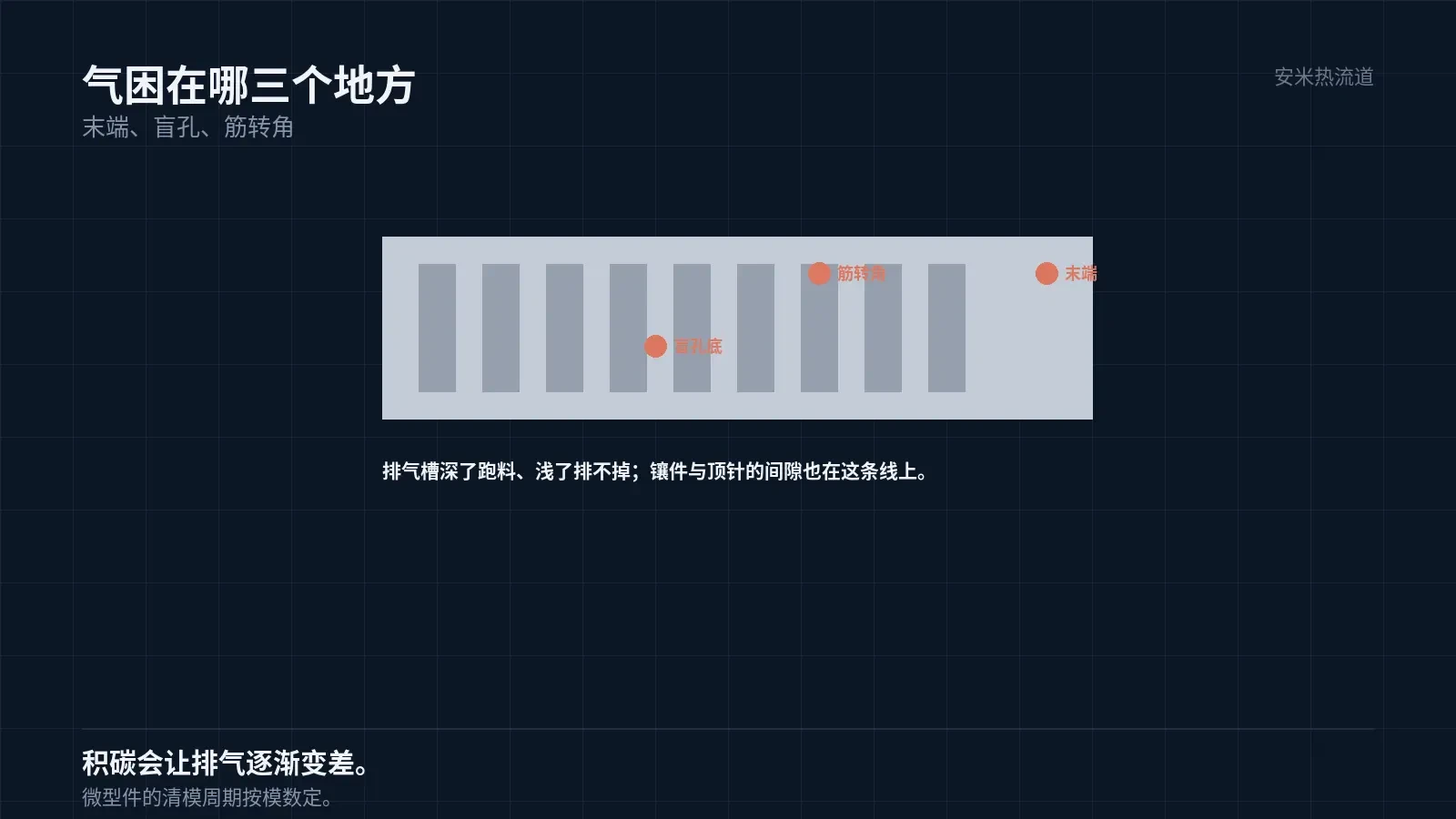
A common practice is cutting shallow grooves along the parting line and venting through ejector pins and insert clearances. Clearances must be controlled to prevent resin intrusion.
For micro parts, vent placement is critical: where does the gas escape? Air traps commonly occur at cavity ends, blind hole bottoms, and deep rib corners.
These locations should be identified via mold flow analysis. Simulation-based gas distribution maps are more accurate than empirical judgment.
Another critical factor for micro parts: the gap between inserts and ejector pins is the primary leakage path. Excessive clearance leads to flash; insufficient clearance impedes venting. Tolerances must be set based on the material.
Micro parts require shorter mold cleaning cycles. Small cavities accumulate carbon quickly, necessitating cleaning every few hundred shots. Delayed cleaning impairs venting and increases defect rates.
Inadequate venting may not show in initial samples but worsens after hundreds of cycles due to carbon buildup on the surface, causing defect rates to rise. Cleaning intervals should be based on this trend.
Gate too small to see
Micro-part gate diameters are typically 0.15–0.3 mm. At this scale, machining precision, tool wear, and clogging are critical concerns.
Small gates create high shear rates. Since LCP is shear-sensitive, excessive shear can degrade the material near the gate, causing embrittlement and reducing part strength.
Large gates leave visible marks and complicate removal. Micro parts often require laser or precision punching for gate removal; residual gate material can interfere with assembly.
Therefore, micro part gates must balance fillability with removability. This optimal point varies by mold and requires trial runs.
Gate machining precision is also critical. A 0.02 mm tolerance on a 0.15 mm gate results in a 13% error; inconsistent gate dimensions across cavities cause uneven filling.
Hot runners are widely used for micro parts. Benefits include eliminating repeated gate removal; drawbacks involve residence time and temperature control. Small shot sizes increase melt residence time in the hot runner, raising the risk of degradation.
Therefore, hot runners for micro parts must feature small channel volume, precise temperature control, and frequent purging. Without these, the hot runner becomes a liability.
Verification: Microscopic Inspection
Visual inspection alone is insufficient for micro part acceptance. Use a microscope or projector to verify terminal wall thickness, gate residue, weld line location, and flash.
Measure dimensions using a toolmaker's microscope or vision measuring system. Calipers lack the accuracy and repeatability required for 0.15 mm wall thicknesses.
Functional testing must comply with customer specifications: insertion/extraction force, contact resistance, and withstand voltage. Micro parts feature low insertion/extraction forces, requiring high fixture precision.
Please provide the part drawing, pitch, wall thickness, number of cavities, and insertion/extraction force requirements. We will verify filling and venting for micro parts before providing a quote.
MATCHED BY MATERIAL AND DEFECT
This article covers stringing, drooling, clogging, and high-heat resins; refer to SD for gate freeze and break-off.
Register for a selection review and quote
Submit part, mold, and material details. Our engineers will evaluate the gate solution per part and provide a quote.
Upload a 2D layout drawing using the form.
Online selection and quote
Scan to register