
PPS in FPC Connectors: Stable Dimensions but Flap Cover Cracking
Material Applications16 min read
On this page
FPC connectors undergo reflow soldering; the body must resist heat without deforming. PPS delivers the best performance: molded at a mold temperature of 150°C, dimensions remain virtually unchanged after oven processing.
However, the flip cover has a high failure rate with PPS. Assembly line feedback reports "cracking after two flips." Dimensional stability and flip cover durability are conflicting requirements for PPS.
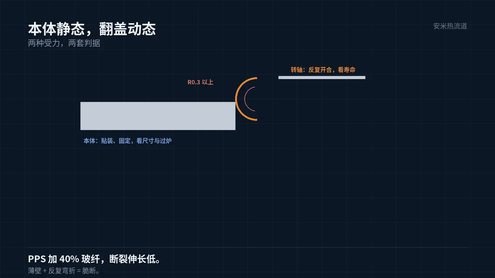
Flip Cover Stress Differs from Body
The body is a static component: mounted, fixed, and stationary. The flip cover is a dynamic component that opens and closes each time an FFC is inserted, with stress concentrated at the hinge and snap-fit.
The hinge wall thickness is only 0.3–0.5mm,, and the snap-fit is even thinner. PPS with 40% glass fiber has high modulus and low elongation at break; thin walls under repeated bending are prone to cracking.
Cracks typically occur at the hinge root and snap-fit corners. These areas are prone to stress concentration and frequently exhibit glass fiber orientation issues.
Thus, dimensional stability applies to the body but not the flip cover. The two components must be evaluated against different criteria.
Structural Changes Can Solve Half the Problem
Adding an R0.3 or larger fillet at the hinge root is the most effective solution. The fillet redistributes stress, moving the fracture point from the root to the mid-section and significantly extending service life.
The second measure is to design the hinge as a "thin-walled arc" instead of a "right-angle thin plate." The uniform bending stress distribution in an arc allows for more flex cycles using the same material.
The third measure is snap-fit interference. Excessive interference causes stiff resistance during each open/close cycle; insufficient interference leads to poor closure. Set PPS interference to "just engaging," not based on PA9T experience.
After implementing these three changes, flip-lid durability typically meets customer requirements. However, if customers require tens of thousands of cycles, PPS remains insufficient and material substitution is necessary.
Hinge diameter must also be sufficient. Hinges smaller than 0.3 mm cannot endure repeated flexing regardless of fillet radius; this is a geometric constraint that process improvements cannot overcome.
The simplest material change is using PA9T for the flip lid while keeping PPS for the body. You must calculate shrinkage differences between the two parts and post-reflow gap changes.
Before switching materials, test the lifespan of current flip lids. Data quantifies material substitution benefits; without it, gains are only psychological reassurance.
If dual-material construction is not acceptable, consider redesigning the flip lid as a "thin-walled arc with an extended hinge." With proper structural design, PPS can withstand several thousand cycles, though not tens of thousands.
A mold temperature of 150°C improves thin-wall performance.
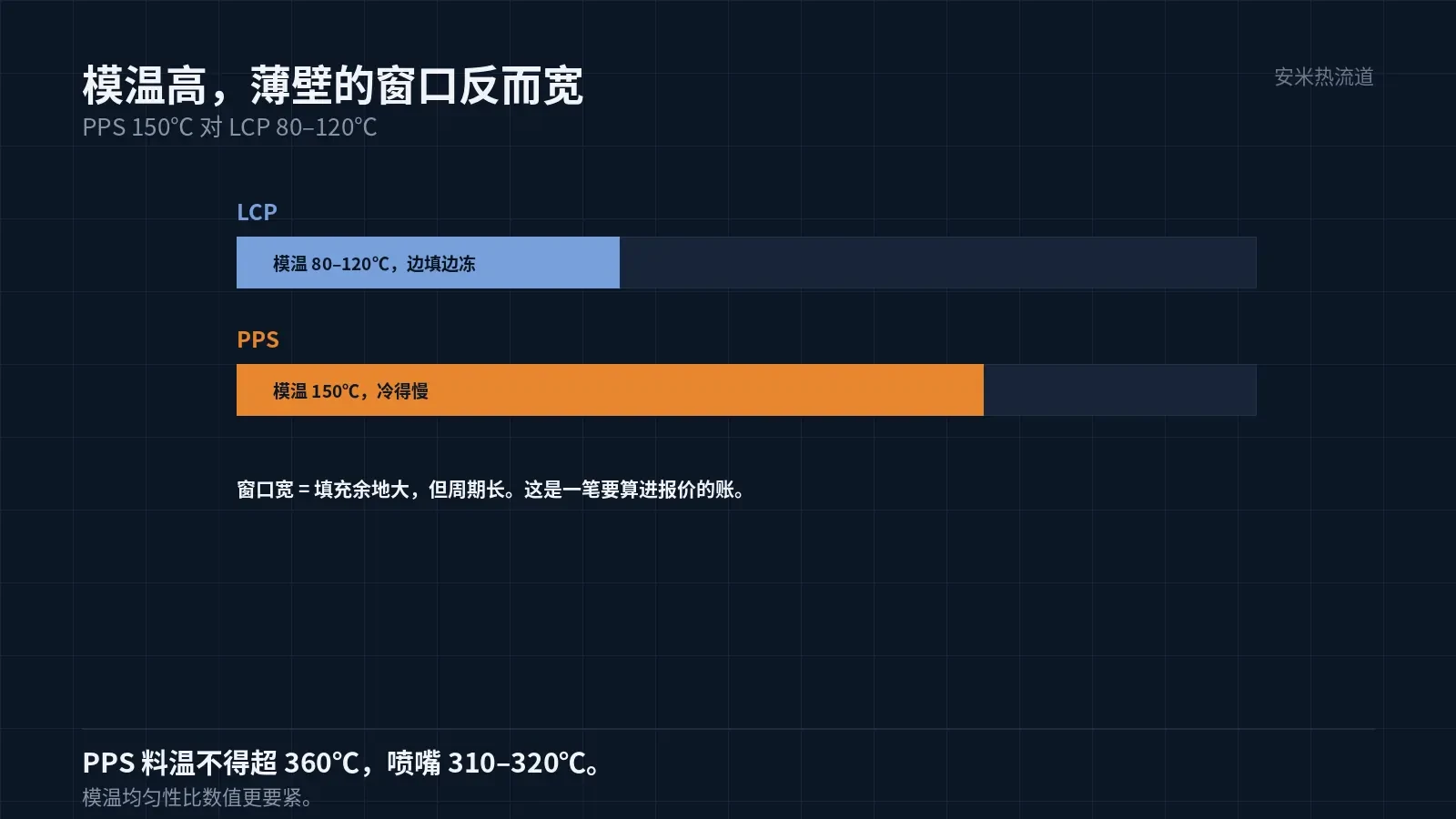
PPS mold temperature of 150°C exceeds LCP's 80–120°C. Higher mold temperatures slow melt cooling in the cavity, enabling thin-wall filling.
This is a hidden advantage of PPS in 0 2mm thin-wall molding: for the same wall thickness, PPS offers a wider filling window than LCP because it resists freezing during filling.
The trade-off is longer cycle time. FPC connectors are small with many cavities; even a slight increase in cycle time significantly reduces capacity. This factor must be included in quotes.
Mold temperature uniformity must also be controlled. On a 150°C mold, a 5°C temperature difference between cavities causes variations in thin-wall filling, which is especially noticeable in multi-cavity molds.
Zoned mold temperature control is more critical for PPS than LCP, as high-temperature gradients have a greater impact on melt flow.
Cooling time is another critical factor. Thin-wall parts require short cooling cycles; however, due to PPS's high mold temperature requirements, cooling time must be recalculated based on actual mold conditions. Insufficient cooling before ejection can cause part deformation, leading to warpage in long sections.
Ejector pin placement requires careful selection. FPC connector terminal slots cannot be ejected; pins must land on the solid sections on both sides and be symmetrical. Single-sided ejection causes one-sided warpage.
Melt Temperature: Do Not Exceed Maximum
PPS melt temperature must not exceed 360°C; set nozzle temperatures to 310–320°C. Exceeding this limit is a hard constraint that causes degradation, leading to black spots and part embrittlement.
For thin-wall parts, operators often raise melt temperature to improve filling. Pushing it above 350°C improves fill but degrades the material. This is the most commonly violated rule on-site.
The correct approach is to fully leverage mold temperature and optimize injection speed, rather than forcing fill with high melt temperatures. The margin for thermal degradation at high melt temperatures is already narrow.
Venting must also be sufficient. Vent depth should be 0.005–0.008 mm. Thin-wall cavities are shallow and require less vent volume, but this depth cannot be omitted; otherwise, end-of-fill burns will occur.
Validation: Open/Close Cycle Life is the Core Metric
Group 1: Tested for open/close cycle life at 1.5 times the customer's required cycles; record crack initiation time and location. Group 2: Post-reflow testing; compare open/close cycle life before and after reflow.
Third Group: Insertion and extraction force measured alongside open/close cycle life; force decay often precedes crack formation.
Please submit the part drawing (including flip cover), open/close cycle requirements, and reflow profile. We will review based on structure and material specifications and provide a quotation upon confirmation.
Another detail: If the flip cover latch uses a single-side snap design, stress concentrates on one side, cutting lifespan in half compared to a double-side snap. Prefer double-side snaps; the cost impact is negligible.
Double-sided snap molds are slightly more complex, but for brittle materials like PPS, this structural investment is far cheaper than subsequent material changes.
MATCHED BY MATERIAL AND DEFECT
This article covers stringing, drooling, clogging, and high-heat resins; refer to SD for gate freeze and break-off.
Register for a selection review and quote
Submit part, mold, and material details. Our engineers will evaluate the gate solution per part and provide a quote.
Upload a 2D layout drawing using the form.
Online selection and quote
Scan to register