
When to Use PEEK in FPC Connectors: The Specific Scenario
Material Applications15 min read
On this page
FPC connectors are thin-walled, high-volume parts with low unit costs. PEEK material and processing expenses rarely justify their use in this category.
Exceptions exist. This article covers only one: when PEEK is truly viable and why it shouldn't be considered otherwise.
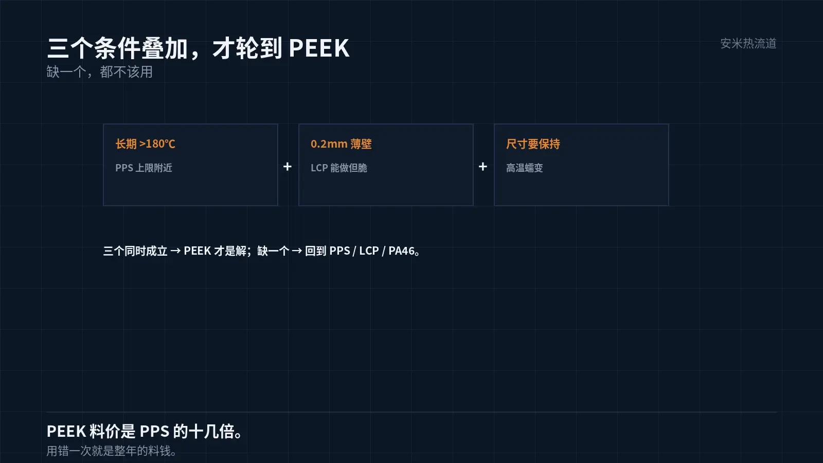
Valid Scenario: Long-Term High Temperature + Thin Wall
In automotive and additive manufacturing applications, FPC connectors may be positioned near heat sources such as engine bays, control boxes, or lighting modules. These locations often experience sustained temperatures exceeding 150°C.
PPS has a long-term service temperature range of 150–200°C, nearing its upper limit; PA46 and PA9T have lower limits. For parts exposed to long-term temperatures above 180°C, PEEK is the only remaining option.
At the same time, the part requires a 0.2mm wall thickness while maintaining dimensional stability. The combination of thin walls, high temperature, and dimensional constraints defines this PEEK application scenario.
Do not use PEEK if any condition is missing. High temperatures with thin walls support thicker PPS structures, while thin walls without high-temperature requirements can be handled by LCP.
This decision is critical because PEEK costs are high; incorrect selection leads to significant annual material waste.
Another often overlooked factor is color. Natural PEEK ranges from light brown to gray, with glass fiber reinforcement making it grayer. If customers need white or black, specific grades must be sourced, which extends lead times.
Color is critical for automotive interior components. While FPC connectors are usually concealed, cosmetic parts require early color confirmation.
Thin-wall + PEEK: Dual processing challenges
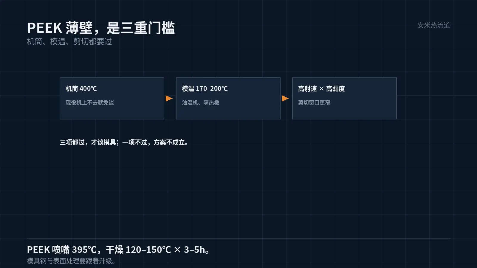
PEEK requires high processing temperatures: nozzle at 395°C, barrel at 375/380–385/390°C, mold temperature at 170–200°C, and drying at 120–150°C for 3–5 hours. The barrel heating capacity must reach 400°C.
Thin-wall parts require high injection speeds, resulting in high shear on the melt at 395°C. Due to PEEK's high melt viscosity, shear effects are more severe than with LCP.
Therefore, the injection profile for thin-wall PEEK parts must be more precise: initial stages should not be too fast to avoid gate burn marks; later stages require packing pressure to prevent end-of-fill shrinkage. The process window is narrower than for LCP.
A mold temperature of 170–200°C improves thin-wall parts by slowing melt cooling and aiding fill. However, high mold temperatures require capable temperature control units, as standard water-cooled systems cannot reach these levels.
Oil-based temperature controllers, high-temperature water circuits, and insulation plates are hidden costs in PEEK solutions. These are often overlooked during quoting but discovered during implementation.
Insulation plates are required. For molds operating at 200°C, missing insulation allows heat to transfer to the injection molding machine platen, raising hydraulic oil temperature and reducing stability. This issue typically appears only during continuous production.
Mold steel selection must also be adapted. High-temperature molds require stricter heat treatment and surface treatment specifications, as standard steels soften under prolonged exposure to 200°C. This factor must be listed separately in mold quotations.
Cost Amortization
Material cost: PEEK costs more than 10× that of PPS. Processing: longer cycle times and lower yields. Equipment: barrel at 400°C, mold temperature at 200°C. Overall, unit costs are typically 2–3× higher than PPS solutions.
This price difference must be amortized over part lifespan and reliability. Automotive parts have stringent lifespan requirements that justify the cost, whereas consumer electronics parts generally do not.
Certification costs also apply. Switching to automotive-grade materials requires re-certification, where time costs often exceed the material price difference. Factor this into your project schedule.
If the cost cannot be justified, a middle ground is to use PEEK only in the hottest local areas and PPS elsewhere. However, for small FPC connector parts, dual-material solutions are often not cost-effective.
Gate and Hot Runner
PEEK is compatible with the SD, VG, and PVG series, but not the TP series. Thin-wall small parts typically use SD series gates, which leave smaller marks and provide clean break-off.
Design the hot runner for 395°C with heating power headroom. For thin-wall parts, minimize runner size; the trade-off between pressure drop and residence time is more critical than in larger parts.
Nozzle bore diameter must match part weight. Oversized bores lead to excessive residence time and material degradation; undersized bores cause high pressure drop and short shots. Mold flow analysis is required—empirical estimation is insufficient.
Purging during shutdown is mandatory. PEEK degrades after prolonged high-temperature exposure. Degraded material darkens and loses fluidity, which can cause black spots if mixed into parts.
Validation: Confirm Equipment First
The first step is equipment verification, not prototyping. Confirm that the barrel reaches 400°C, the mold temperature controller reaches 200°C, and the hot runner reaches 395°C. If any parameter fails to meet these values, the solution is invalid.
Step 2: Small-batch trial molding. Conduct flow length ratio tests on thin-wall areas to determine the filling window. Step 3: Long-term aging. Test at operating temperature for 500h and 1000h, to measure dimensional and mechanical retention rates.
Send us the operating temperature curve, part drawings, and existing equipment parameters. We'll first assess feasibility across all three conditions, then verify the gate design, and provide a quote upon confirmation.
If only two of the three conditions are met, use structural modification instead. Convert the hottest section to a metal insert or add thermal insulation so the plastic component does not directly withstand high temperatures.
MATCHED BY MATERIAL AND DEFECT
This article covers stringing, drooling, clogging, and high-heat resins; refer to SD for gate freeze and break-off.
Register for a selection review and quote
Submit part, mold, and material details. Our engineers will evaluate the gate solution per part and provide a quote.
Upload a 2D layout drawing using the form.
Online selection and quote
Scan to register