
Why LCP Still Warps in 0.2mm Wall Thickness FPC Connectors
Material Applications16 min read
On this page
FPC and FFC connectors are the thinnest connector type: body wall thickness is often 0.2mm,, overall length ranges from 10 to 20 mm, and a row of terminal slots with 0.3 mm pitch must be machined on them.
LCP is the mainstream material for these parts because its flowability alone supports such thin walls. However, once wall thickness hits its limit, warpage becomes a new challenge. This article explores the trade-off between thin walls and warpage.
Thin-wall filling depends on speed.
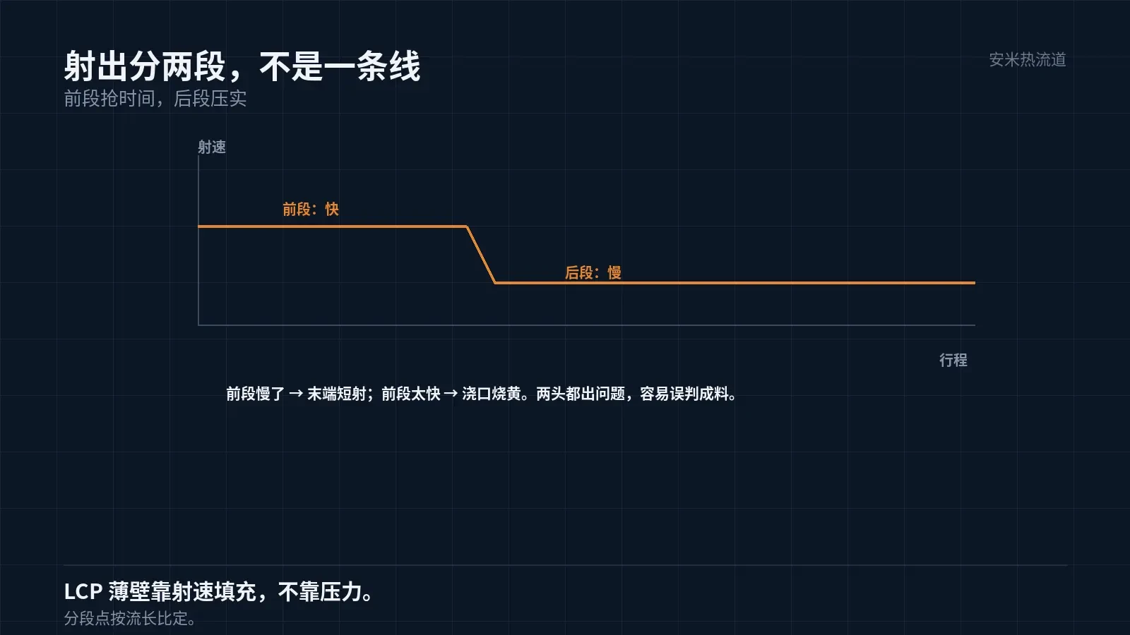
For a 0.2mm wall, melt travel time from gate to end is often only tens of milliseconds. Filling depends on speed, not pressure—if injection speed is too low, the melt front freezes in the channel.
LCP has low viscosity, enabling 0.2mm walls. However, its low viscosity also makes it shear-sensitive; excessive injection speed causes shear heating at the gate, leading to yellowing.
Therefore, the injection profile for thin-wall LCP parts requires two stages: a fast stage to fill the channel before solidification and a slow stage to pack the end. A single-speed profile cannot produce stable parts.
The transition point is set based on the part's flow length ratio. For high ratios, extend the fast stage; for low ratios, shorten it to prevent gate overheating.
If the transition point is set incorrectly, symptoms include yellowing near the gate and short shots at the end. These issues occurring together can easily lead to misdiagnosis of material problems on-site.
Warpage: A common issue with long parts
FPC connectors are elongated, measuring 15 mm in length and 4 mm in width, yielding an aspect ratio of approximately 4:1. This geometry amplifies directional shrinkage differences along the length.
LCP shrinkage is 0.10%/0.40%, a fourfold difference. Over a 15mm length, the absolute differential between directions reaches tens of microns, causing bow warpage in long parts.
Bow warpage causes issues by creating a 'high center, low ends' condition. During mounting, the center makes contact first while the ends remain suspended, resulting in failed or cold solder joints.
Board-to-board warpage is a coplanarity issue, while FPC warpage is a mounting issue. These failure modes require different acceptance criteria: measure coplanarity for the former and inspect solder joints after mounting for the latter.
Therefore, dimensional reports for FPC connectors must include a "post-mount inspection" group; checking individual part dimensions alone is insufficient.
Gate: Single vs. Double
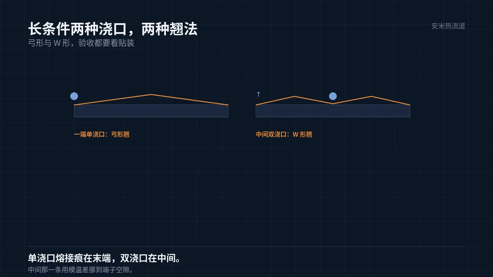
For long parts, gate placement offers two options: single-end gating or dual-center gating. Single-end gating results in longer flow paths and lower end pressure, causing unidirectional bow warpage. Dual-center gating shortens flow paths and provides symmetry, shifting the warpage pattern to a 'W-shape.'
A single gate produces only one weld line (at the end) but causes high pressure loss. Double gates offer better pressure control, but create a weld line in the center—often where terminals are most dense.
Our experience indicates that a single gate works for up to 20 terminals, while double gates are recommended for over 30. Adjusting the mold temperature can shift the central weld line into the gaps between terminals.
This approach requires coordinated mold temperature zoning: the weld line location depends on the temperature difference between the two sides. A 3–5°C difference can shift the weld line by 1mm.
Mold temperature zoning requires cooling channel design before mold opening; changes cannot be made afterward. This is especially critical for FPC connectors due to their narrow geometry, which leaves little room for cooling channels.
Slider fit uses separate tolerances.
Most FPC connectors feature a slider or flip cover. The cover is a separate component with clearance relative to the body. Body warpage directly reduces this clearance.
If the body warps by 0.05mm and the cover fit clearance is only 0.06mm,, assembly will jam. These issues appear on the assembly line as "unable to insert" or "cover does not seal after insertion."
Therefore, body and cover tolerances must be specified together, not separately. The cover is often made of LCP; consistent shrinkage between both parts ensures a stable fit.
If the cover uses a different material, shrinkage differences can cause fit issues after assembly: it may fit initially but jam after reflow soldering. This is often overlooked during material substitution evaluations.
Verification: Single-part and assembly levels
Single-piece layer: Measure length, width, terminal pitch, and warpage. Assembly layer: Install cover, insert FFC, and measure retention and insertion/extraction forces. Both layers are required; omitting either results in an incomplete process.
Warpage measurement methods must be standardized. Results vary significantly between free-state flat placement and post-flattening measurements. We follow the customer's method; discrepancies prevent agreement.
Mold temperature is another key factor. For LCP (mold temp 80–120°C), longer flow paths benefit from higher mold temperatures, which slow melt cooling and allow pressure to reach the end of the part more effectively, reducing warpage. However, higher mold temperatures also increase cycle time; the optimal setting depends on your part tolerance requirements.
Mold temperature uniformity is critical. An 8°C difference between the ends of a long flow path causes inconsistent shrinkage, leading to twisting instead of bowing. Twisted parts are harder to correct because the deformation direction is unpredictable.
Submit the component drawing (including cover), terminal count and pitch, mounting method, and reflow profile. We will verify gate design and mold temperature zoning based on aspect ratio and provide a quote upon confirmation.
A common issue in mass-producing FPC connectors is "first article passes, batch drifts." Drift typically results from mold temperature fluctuations during production, so mold temperature curves must be recorded throughout continuous manufacturing.
MATCHED BY MATERIAL AND DEFECT
This article covers stringing, drooling, clogging, and high-heat resins; refer to SD for gate freeze and break-off.
Register for a selection review and quote
Submit part, mold, and material details. Our engineers will evaluate the gate solution per part and provide a quote.
Upload a 2D layout drawing using the form.
Online selection and quote
Scan to register