
PPS Overmolding on Metal Inserts in HV Connectors: Causes of Interface Cracking
Material Applications17 min read
On this page
High-voltage connectors include metal inserts such as shielding rings, grounding tabs, and reinforcement plates. The plastic component must overmold these inserts to ensure insulation and secure fixation. This overmolded region is the most vulnerable part of the entire assembly.
PPS offers optimal temperature resistance and dimensional stability for high-voltage components, yet cracking at the overmolding interface remains a significant concern. This article covers three key aspects of this interface.
Interface Cracking: First, Consider Thermal Expansion Differences
PPS with 40% glass fiber has a low coefficient of thermal expansion. Although metal inserts also exhibit low thermal expansion, the two materials do not perfectly match. Temperature changes induce shear stress at the interface.
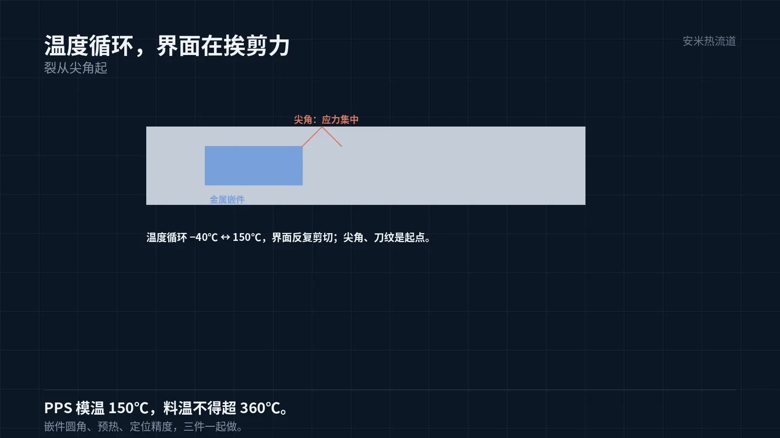
High-voltage components must withstand temperature cycling from -40°C to 150°C. Within this range, repeated shear stress at the interface causes cracks to initiate at weak points first.
Crack initiation typically occurs at sharp corners, threads, or machining marks on the insert. These areas exhibit high stress concentration factors that exceed the interface bond strength.
Therefore, insert design is more critical than material selection: use rounded corners, avoid sharp edges, and maintain moderate surface roughness. Excessively low roughness results in insufficient mechanical interlocking; excessively high roughness causes stress concentration.
This specification must be defined on the insert drawing. Modifying the insert after mold opening requires remaking the entire mold set.
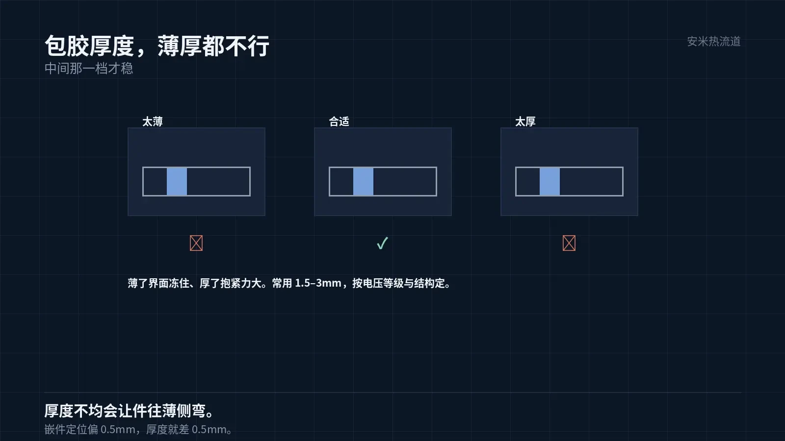
Overmolding thickness determines success or failure.
If the overmold layer is too thin, melt flow velocity on the insert surface increases and cooling accelerates. The melt at the interface freezes before proper wetting occurs, resulting in a weak bond.
If the overmold layer is too thick, excessive shrinkage generates high clamping force on the insert during cooling and elevated interfacial stress. Both conditions lead to cracking, though via different mechanisms.
Common overmold thicknesses range from 1.5–3 mm. Specific values depend on the part's voltage rating and structure; consider both mechanical strength and creepage/clearance distances.
Uniformity of the overmold layer is also critical. A thickness difference of 1 mm on one side versus 3 mm on the other causes the thicker side to shrink more, bending the part toward the thinner side and concentrating interfacial stress there.
Therefore, precise insert positioning within the mold is critical. A 0.5 mm positional deviation causes a 0.5 mm variation in overmold thickness, resulting in uneven interfacial stress.
A mold temperature of 150°C improves the interface.
The PPS mold temperature of 150°C is significantly higher than that for LCP. Higher mold temperatures slow melt cooling on the insert surface, extending contact time and improving interfacial strength.
This is an advantage of PPS in overmolded parts: for identical structures, PPS typically provides better interfacial strength than LCP.
However, higher mold temperatures require adequate insert preheating. If cold inserts enter a 150°C mold, the melt at the contact surface still undergoes rapid quenching; preheating mitigates this effect.
Preheat temperature should be close to the mold temperature and must not significantly exceed it. Excessive preheating prevents solidification at the interface, causing damage during demolding.
Fixation method matters. For screw-fixed inserts, thread corners are stress concentration points; for snap-fit inserts, allow sufficient elastic travel to prevent interference from thermal expansion.
Large parts require uniform ejection. Insufficient ejector pins cause high local ejection forces and residual stress, increasing the risk of cracking at the overmold interface. Position pins symmetrically and avoid inserts.
Overmolded parts require sufficient draft angles. The side in contact with the insert experiences higher demolding resistance; insufficient draft can damage the interface, creating a potential site for future cracks.
Melt and mold temperatures must be coordinated. Low mold temperature causes rapid freezing at the interface, creating voids between the overmold layer and insert; high mold temperature leads to demolding damage. The optimal range is determined through trial molding.
Preheating is mandatory for high-pressure components, not optional. Skipping this step reduces interface strength by one grade and causes temperature cycling test failures.
Melt Temperature: Upper Limit Must Not Be Exceeded
PPS melt temperature must not exceed 360°C; nozzle temperature should be set to 310–320°C. This is a hard limit—exceeding it causes material degradation.
Degraded material flows better and fills more easily, but strength and insulation drop. Increasing melt temperature on-site to ensure complete filling trades reliability for yield.
Fill high-voltage components using mold temperature, runner design, and injection speed—not melt temperature. Melt temperature tolerance is already limited.
Vent depth: 0.005–0.008 mm. Larger parts have bigger cavity volumes and need higher venting capacity. Ensure sufficient vents to prevent burn marks at the end of fill.
Burn marks on high-voltage components cause two problems: cosmetic rejection and degraded insulation. Charred material acts as conductive contamination.
For large parts, injection speed must be staged: start slow for smooth melt entry, accelerate in the middle stage to fill before solidification, and slow down at the end for packing. A single constant speed cannot accommodate both thin-wall and thick-wall sections.
Validation: Thermal cycling is the primary test
First thermal cycling group: -40°C to 150°C, following the customer-specified cycle counts, with intermediate checkpoints for insulation and dielectric withstand tests. The second group involves cross-section analysis to check interfaces for voids or cracks.
Group 3 performs vibration testing: interface cracks propagate under vibration. Among the three groups, Group 1 best exposes issues.
Empirical guideline for interfaces: Overmold thickness below 1.5 mm significantly reduces thermal cycling pass rates; above 3 mm, excessive shrinkage-induced clamping force causes cracking. Intermediate thicknesses offer the most stability.
Additionally, sharp corners on inserts pose risks in drawings. Apply chamfers or radii wherever possible; if not feasible, include mold-side relief to prevent direct melt impact on sharp corners.
Submit the insert drawing, overmolding thickness, thermal cycling conditions, and voltage rating. We will verify based on interface and mold temperature, then provide a quote upon confirmation.
MATCHED BY MATERIAL AND DEFECT
This article covers stringing, drooling, clogging, and high-heat resins; refer to SD for gate freeze and break-off.
Register for a selection review and quote
Submit part, mold, and material details. Our engineers will evaluate the gate solution per part and provide a quote.
Upload a 2D layout drawing using the form.
Online selection and quote
Scan to register