
PA9T in HV Connectors: Moisture Absorption as an Electrical, Not Cosmetic, Issue
Material Applications17 min read
On this page
High-voltage connector failures are rarely caused by cosmetic defects. Most involve reduced insulation resistance, dielectric breakdown during withstand voltage testing, or creepage after prolonged use. The root cause is often moisture in the material.
PA9T has a water absorption rate of 0.19%, which is low for high-temperature nylons. However, insulation in high-voltage components is highly sensitive to moisture levels. This article explains the relationship between moisture and insulation performance.
Moisture Conducts Electricity in Polyamides
When polyamides absorb water, molecules penetrate the amorphous regions, increasing inter-chain spacing and facilitating ion migration. Macroscopically, this leads to lower volume resistivity and reduced dielectric strength.
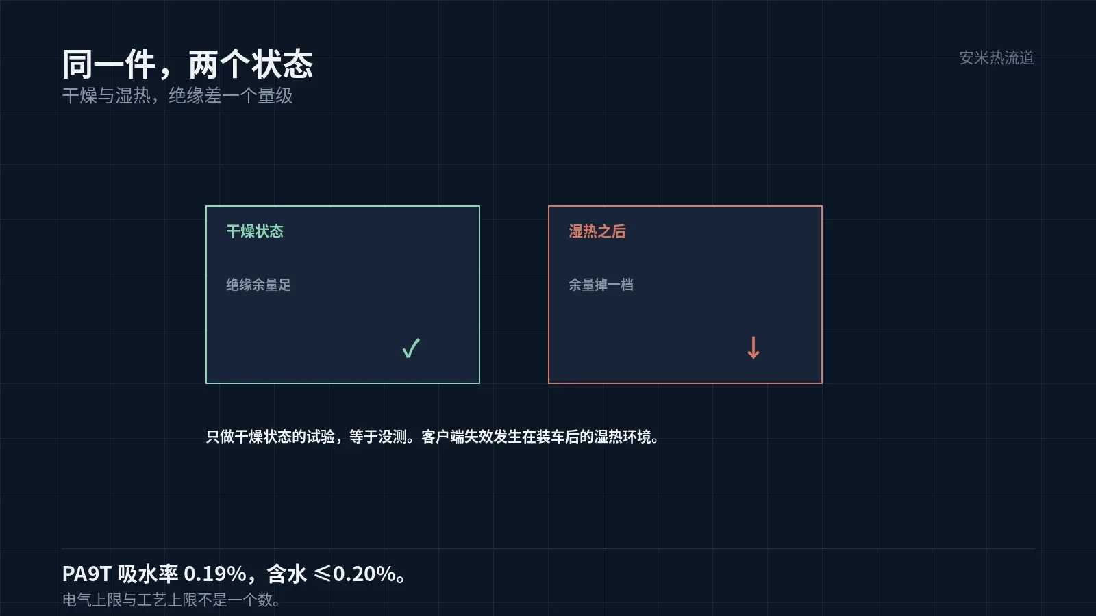
A 0.19% water absorption rate may appear negligible. However, in the thin walls and creepage distances of high-voltage components, this moisture level is enough to reduce insulation resistance by an order of magnitude.
Therefore, acceptance testing for high-voltage connectors must include electrical tests under both dry and damp-heat-cycled conditions. The difference between these two sets of data reflects the component's true safety margin.
Testing only under dry conditions is effectively no test. Failures on the customer side often occur in damp heat environments after vehicle assembly.
Drying Is a Process, Not Just a Step
PA9T drying: 70–90°C for 4–8 h, moisture ≤0.20%. This 0.20% limit applies to the injection molding process, not electrical performance.
To ensure electrical performance, moisture levels must be kept low. The specific target varies by customer standard; since requirements differ across customers, no single universal value can be defined.
The path from the dryer to the machine must be sealed: use an insulated hopper, desiccant, and enclosed transfer. Exposure in the workshop causes re-moisturizing within hours, rendering prior drying ineffective.
This factor is more critical for high-voltage components than standard ones, as failures are latent: issues may surface months after assembly, leading to extremely high traceability costs.
Records must be detailed: drying curve per batch, exit temperature, time to line start, and workshop humidity. These four data points clarify responsibility when issues arise.
Mold Temperature and Crystallinity: Effects Beyond Dimensions
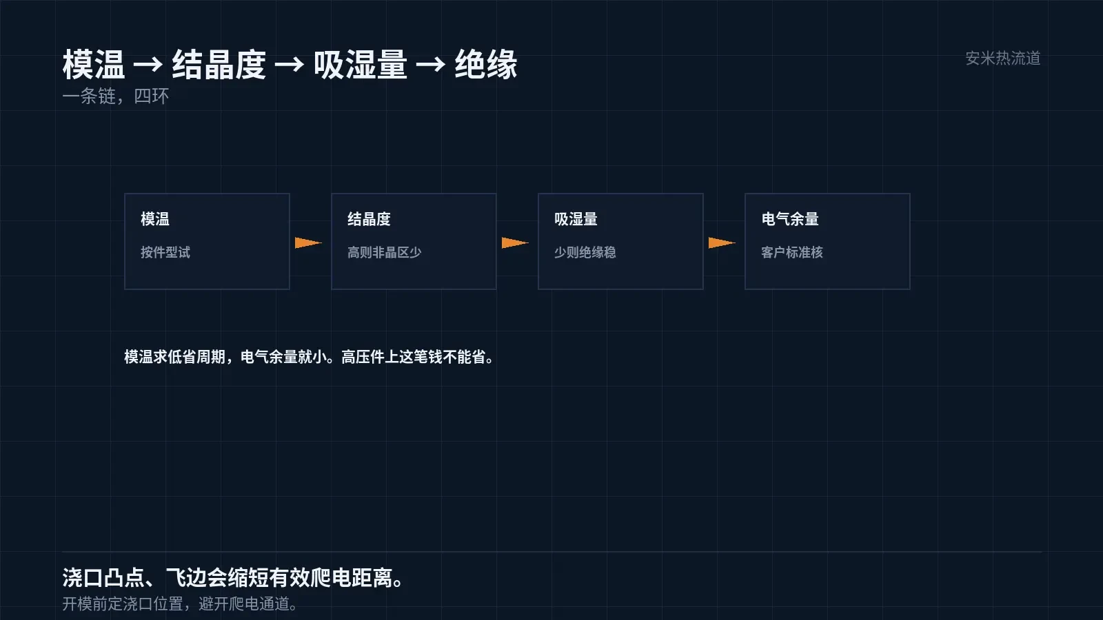
No recommended mold temperature is provided by the PA9T manufacturer; it must be determined through trial based on part geometry. Mold temperature affects crystallinity, which in turn influences moisture absorption rate and dimensional stability.
Parts with low crystallinity have a higher amorphous phase ratio, absorb more moisture, and are more susceptible to insulation degradation. Therefore, do not simply minimize mold temperature; while this shortens cycle time, it reduces electrical margin.
For high-voltage components, use a higher mold temperature to ensure adequate crystallization. Exact values must be determined through moisture absorption and electrical testing on first articles, not based solely on experience.
This undermines cost-reduction efforts. Higher mold temperatures and longer cycles raise unit costs but ensure sufficient electrical margin. For high-voltage components, these costs are unavoidable.
Structure and Creepage Distance
High-voltage components must meet creepage distances specified by customer standards; we manufacture strictly per drawings. However, molding processes impact actual distances: flash, flow marks, and gate protrusions reduce effective creepage length.
Gate protrusions are the most common issue. A protrusion height of 0.2 mm reduces the effective creepage distance by 0.2 mm; this cannot be ignored for high-voltage components.
Therefore, gate locations must avoid creepage paths or require flattening protrusions. Flattening adds post-processing costs; determine the location before mold fabrication.
Flash can have a similar effect. Parting lines on high-voltage components must be flat, and clamping force must be adequate. Even minor flash acts as a "point" on the conductive path, concentrating the electric field.
Flame retardancy and tracking resistance are verified only against customer standards; no specific codes or values are provided. Material compliance must be validated using the customer's test conditions.
Gate and Hot Runner
For PA9T, only the SD Series is recommended. High-voltage components typically have fewer cavities and heavier part weights; the SD Series delivers adequate flow capacity while minimizing gate marks.
Barrel: 280–320/285–330/290–340°C; Nozzle: 300–350°C. Use only grade-specific data sheets for temperature settings; do not apply parameters from other nylons.
Hot runner zoning is required, especially for large parts. Control the nozzle, manifold, and gate zones separately to ensure actual temperatures in each zone stay within the specified range.
Control residence time. PA9T degrades if held at high temperatures too long; the resulting polar degradation products lead to reduced insulation performance after moisture absorption. This is a hidden chain reaction.
Large parts have larger runner volumes and longer residence times; these must be calculated based on part weight. For a 60 g part, small runners cause high pressure drop, while large runners increase residence time; both factors require verification.
Venting requires special attention for large parts. In cavities with large volumes, air at the end must be vented. Determine vent quantity and location using mold flow analysis to prevent burn marks at the end, which also affect insulation.
Validation: Electrical and Damp Heat Testing Combined
Group 1 (Dry State): Insulation resistance and dielectric strength. Group 2 (After Damp Heat): Same two tests to evaluate degradation. Group 3 (Long-term): Temperature cycling per customer requirements with intermediate measurements.
After completing all three groups, the part's electrical margin becomes clear. If the margin is insufficient, revisit material selection and mold temperature; do not attempt to compensate during assembly.
If electrical margin is insufficient, verify the actual creepage distance rather than relying on drawing values. Flash, protrusions, and flow marks reduce effective distance; measured values are often lower than those shown in drawings.
Please provide the part drawing, creepage distance requirements, electrical test conditions, and workshop humidity records. We will verify moisture absorption and mold temperature before confirming pricing.
MATCHED BY MATERIAL AND DEFECT
This article covers stringing, drooling, clogging, and high-heat resins; refer to SD for gate freeze and break-off.
Register for a selection review and quote
Submit part, mold, and material details. Our engineers will evaluate the gate solution per part and provide a quote.
Upload a 2D layout drawing using the form.
Online selection and quote
Scan to register