
What Enables 'Instant' Gate Response?
Material Applications16 min read
On this page
Variable temperature is easy to say but hard to achieve quickly. A half-second delay causes the gate state to slip through.
Speed depends on two physical quantities: thermal inertia and thermal equilibrium.
What is Thermal Inertia?
Thermal inertia describes how quickly a heating element heats up or cools down. It depends on mass, specific heat capacity, and the thermal conduction path.
Greater mass slows heating and cooling. A thick heater block takes tens of seconds to rise from 200°C to 300°C, while a thin heater plate requires only a few seconds.
Therefore, nozzles requiring FHFC must use low-mass heating elements placed as close to the gate as possible.
Proximity is critical. Each additional layer of material between the heating element and the gate increases thermal resistance, slowing response time.
This explains why variable temperature zones are positioned near the gate, closest to the nozzle tip: it is a physical constraint, not a design preference.
This constraint also explains why rapidly varying the temperature of an entire hot runner nozzle is not engineeringly feasible. Increased mass hinders high-speed response.
As a result, most market solutions use localized rapid temperature control at the nozzle tip while maintaining constant temperature in the runners. These two zones are controlled independently to fulfill their specific functions.
Another advantage of this zone is that a constant runner maintains stable melt viscosity and pressure, ensuring consistent filling.

What is Thermal Equilibrium?
Thermal equilibrium is reached when heat input matches heat dissipation. Temperature stabilizes only at this point.
For FHFC nozzles, heat is removed by the mold during cooling. The cooling rate depends on mold temperature, coolant flow rate, and contact area.
Therefore, cooling speed depends on both the nozzle and the mold. Insufficient mold cooling prevents effective temperature reduction, regardless of nozzle performance.
This is often overlooked: if the mold's cooling channels don't align with the fast thermal cycling nozzle, effectiveness drops by half.
Mold water channel design requires independent cooling near the gate. Sharing a circuit with the cavity couples gate cooling to cavity requirements.
An independent circuit enables flow and temperature adjustment for the gate. This must be reserved during mold design; it cannot be modified after fabrication.
For variable-temperature system projects, the hot runner and mold must be designed together. Separate bidding often leads to incompatibility.
Conversely, if mold cooling is too aggressive, heating compensation during the heating phase cannot keep up. The gate temperature fails to rise, causing filling issues.
Two Time Constants
Heating and cooling each have a time constant. Both must be small for the variable temperature system to keep pace with the cycle.
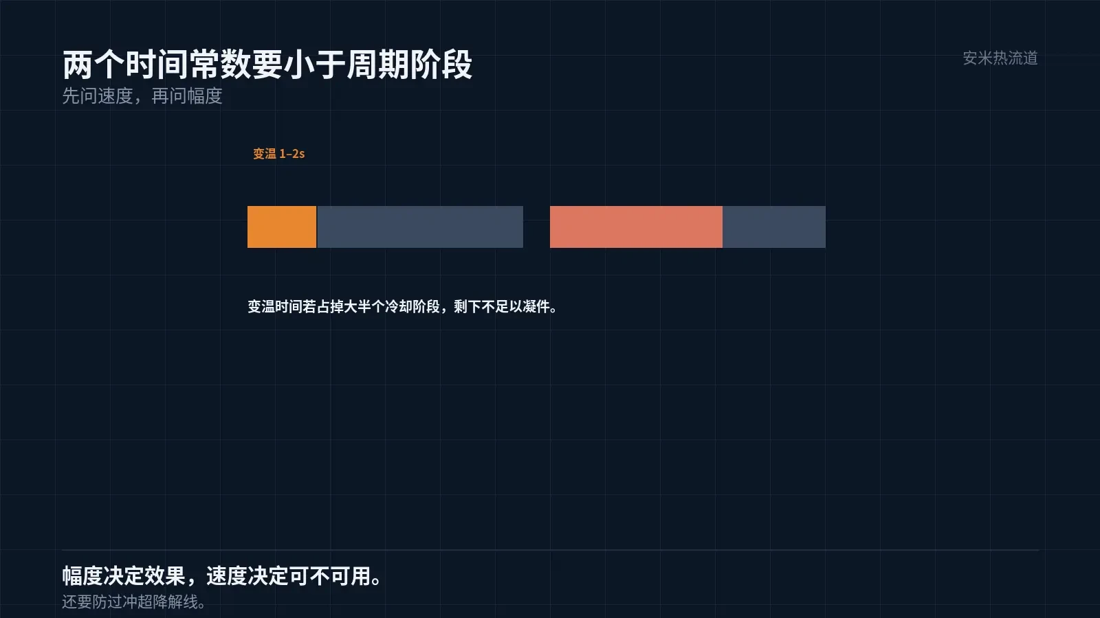
The variable temperature duration must be significantly shorter than the corresponding phase in the molding cycle. For a 20-second cycle with an 8-second cooling phase, variable temperature must complete within 1–2 seconds.
If variable temperature takes 5 seconds, it consumes most of the cooling phase and leaves insufficient time for part solidification. In this case, variable temperature becomes a burden.
Therefore, the first question when selecting a solution is not "how many degrees it can change," but "how long one change takes."
The second question is "How many degrees can it change?" Amplitude determines effectiveness; speed determines feasibility.
Amplitude must be sufficient to produce visible results. If the temperature difference is too small, gate condition changes are negligible—effectively equivalent to no variable temperature.
However, larger amplitudes increase thermal stress. Repeated thermal shock shortens heater and nozzle tip lifespans, requiring trade-offs.
Empirical practice sets amplitude by material: smaller for low-temperature materials, larger for high-temperature ones. Specific values must be calculated based on thermal balance; no universal value applies.
Another criterion is "consistency": temperature curves across ten consecutive cycles must overlap. If they do not, the system is unstable and amplitude analysis is invalid.
Even if curves overlap, stability must carry over to the next week and batch. Stability is a long-term attribute, not achieved in a single machine setup.
Control Precision
Rapid temperature changes require precise control. Sensor placement, response time, and lag compensation in the control algorithm all influence the actual curve.
Place temperature sensors near the gate. Measuring the heater body reflects the heater's temperature, not the gate's, causing a discrepancy.
Control systems must account for lag. Heater response is delayed; if the controller adjusts based on pre-delay temperatures, overshoot occurs.
Overshoot causes the gate temperature to exceed the material's degradation limit. PA46 degrades above 320°C; an overshoot of 10°C causes issues.
Therefore, the control system represents a major cost component in FHFC systems and cannot be compromised.
Material Compatibility
Different materials have different temperature ramp-rate requirements. LCP solidifies rapidly and needs faster temperature changes; PA46 has a narrow processing window and requires precise temperature control.
PPS viscosity is insensitive to temperature (it does not increase significantly even with prolonged residence time). The benefits of variable temperature are smaller than those for LCP but still improve surface quality.
PEEK has a melting point of 343°C and requires a mold temperature of 170–200°C. Thermal balance calculations differ entirely from those for low-temperature materials.
Therefore, the answer to whether "one system can process all materials" is typically no. The system must be configured based on the material and part geometry.
Send us the material, cycle time, mold temperature, and gate type. We'll perform thermal balance calculations and provide a quote upon confirmation.
MATCHED BY MATERIAL AND DEFECT
This article covers stringing, drooling, clogging, and high-heat resins; refer to SD for gate freeze and break-off.
Register for a selection review and quote
Submit part, mold, and material details. Our engineers will evaluate the gate solution per part and provide a quote.
Upload a 2D layout drawing using the form.
Online selection and quote
Scan to register