
Why Are Type-C Housings Both Thin and Aesthetically Demanding?
Material Applications17 min read
On this page
Type-C connector housing with 0.4 mm wall thickness; cosmetic surface must be free of weld lines, color variation, and flow marks.
These three constraints push material and process limits to the edge.
0.4 mm Wall Thickness
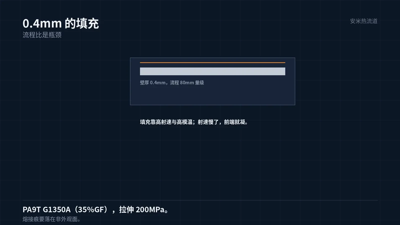
The Type-C interface has standardized dimensions. The housing covers the terminals, and space constraints limit the wall thickness to approximately 0.4 mm.
The 0.4 mm wall thickness leads to a high flow ratio and challenging filling. PA9T offers moderate fluidity, which is compensated by increasing the injection speed and mold temperature.
PA9T grade with 35% glass fiber reinforcement delivers 200 MPa tensile strength and 10 GPa flexural modulus, providing the rigidity needed for the 0.4 mm wall.
Unreinforced grades provide better fluidity but lack rigidity, causing deformation during insertion and removal. Glass fiber reinforcement is therefore required.
Glass fiber adds rigidity but creates cosmetic issues like exposed fibers and prominent weld lines. This trade-off is the core challenge.
Thin-walled parts face another challenge: rapid melt cooling during flow leads to low front-end melt temperatures and weak weld line strength.
Therefore, gate locations for thin-wall parts should place weld lines in non-load-bearing areas, such as non-cosmetic side surfaces.
Weld line strength is typically only 50% of the base material. Thin-walled parts are inherently weak; locating weld lines on load-bearing surfaces creates a risk.
Three "Don'ts" for Appearance
Weld lines: In housings, weld lines typically appear opposite the socket. This area is on the front face and must remain free of marks.
Color Variation: Uneven glass fiber distribution creates light and dark patches, especially noticeable on light-colored parts.
Flow Marks: Variations in melt flow speed create ripples on the surface. These defects occur most frequently on thin walls.
Solutions vary by issue: weld lines depend on mold temperature and injection speed; color variation depends on glass fiber dispersion and melt temperature; flow marks depend on injection speed and gate design.
Therefore, tuning appearance-critical components requires balancing multiple parameters rather than adjusting a single one.
Tuning sequence matters: set mold temperature first, then injection speed, and finally packing pressure. Reversing this order causes parameter conflicts.
This step is often skipped during mold trials. Rushing leads to changing three parameters simultaneously, making it impossible to identify which one had an effect.
For cosmetic parts, keep a "parameter–appearance" log during mold trials. Compare photos from different locations on the same part to identify trends.
Mold Temperature
Higher mold temperatures slow melt cooling, enabling sufficient molecular chain diffusion at weld lines and minimizing their visibility.
Higher mold temperatures allow glass fibers to relax, reducing fiber exposure and improving surface gloss. This is a common technique for cosmetic parts.
Higher mold temperatures extend cycle times and may affect part dimensions. Adjust based on tolerances; avoid maximizing temperature blindly.
The manufacturer does not specify mold temperature for PA9T. Set it based on part type: use high values for cosmetic parts and medium values for structural parts.
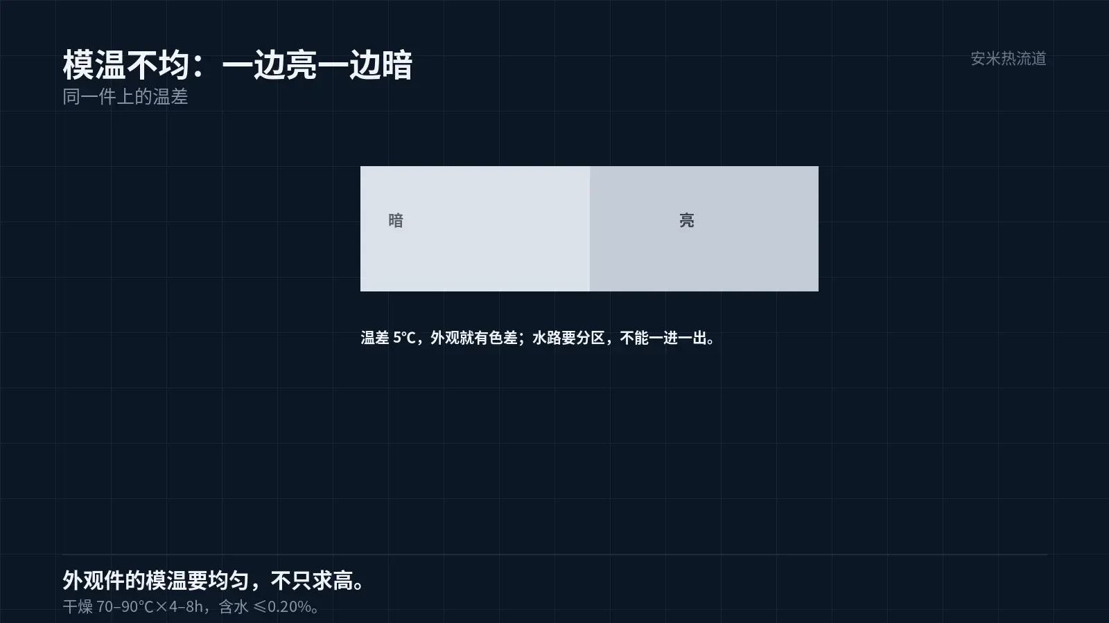
Mold temperature uniformity matters more than the absolute value. A 5°C variation across a single part leads to inconsistent gloss (bright vs. dark areas).
Drying and Hydrolysis
PA9T drying: 70–90°C for 4–8 hours, moisture content ≤0.20%.
Insufficient drying leaves moisture in the melt, leading to hydrolysis that produces gas and silver streaks on the surface. Silver streaks are critical defects for cosmetic parts.
Therefore, cosmetic parts require stricter drying than structural parts. Dried material must be sealed and kept from exposure in the workshop.
Workshop humidity must also be controlled. In southern regions during the rainy season, materials absorb moisture even in the hopper; a dehumidifying dryer is required.
This factor is often overlooked during quoting. Dehumidification equipment costs must be included in the mold and process plan.
Residence time in the hopper must also be controlled. Material left too long in a hot-air dryer will oxidize and yellow, which is especially noticeable on light-colored parts.
Therefore, dryer capacity must match machine consumption. Excessive capacity causes material to sit overnight, leading to yellowing the next day.
Light-colored part hoppers must also be shielded from light. Prolonged exposure to workshop lighting through transparent hoppers can cause color fading.
Gate and Runner
The gate on the housing is typically located opposite the socket or at the bottom. Placing it on the front face leaves a visible gate mark that cannot be removed.
A small gate causes high pressure loss; a large gate leaves a visible mark. A balance must be struck, typically 0.6–0.8mm..
Runners should have rounded corners to prevent melt stagnation at turns. Stagnant material degrades and causes discoloration on the part.
The SD series is suitable for hot runners. For PA9T, only the SD series is recommended per AM industry specifications; TP series, VG series, and PVG are not recommended.
The cold slug in the SD must be tightly controlled. If it's too large, the gate nub on the part will protrude; if too small, drool will occur.
Validation
Housing validation covers: dimensions (socket fit), appearance (three "must-nots"), insertion/extraction force, and weather resistance.
Insertion and extraction force is the most common failure mode. Insufficient housing rigidity causes loosening after multiple cycles.
Weather resistance includes high/low temperature cycling and damp heat. PA9T's low water absorption minimizes dimensional changes after damp heat testing, a key advantage.
Appearance acceptance requires defined standard samples. Stating only "no obvious defects" leads to differing interpretations between supplier and customer.
Insertion/withdrawal force testing requires standard connectors and measures the first and Nth cycles. Attenuation at the Nth cycle reflects housing durability.
Test fixtures must be standardized. Different fixtures can cause measurement deviations exceeding 10%.
Durability tests for insertion and withdrawal are typically performed according to customer-specified cycle counts, such as 10,000 cycles. Incomplete test results are extrapolated based on sampling inspections.
Please provide part drawings, wall thickness, appearance grade, and insertion/withdrawal force requirements. We will verify material and gate selection before issuing a quotation.
MATCHED BY MATERIAL AND DEFECT
This article covers stringing, drooling, clogging, and high-heat resins; refer to SD for gate freeze and break-off.
Register for a selection review and quote
Submit part, mold, and material details. Our engineers will evaluate the gate solution per part and provide a quote.
Upload a 2D layout drawing using the form.
Online selection and quote
Scan to register