
Why Must Camera Module Bases Withstand Reflow Soldering?
Material Applications15 min read
On this page
Most components on mobile phone motherboards undergo reflow soldering. If the base cannot withstand oven temperatures, process changes are required, significantly increasing costs.
PPS's ability to withstand reflow soldering is a key advantage in consumer electronics.
Reflow Soldering Temperature Profile
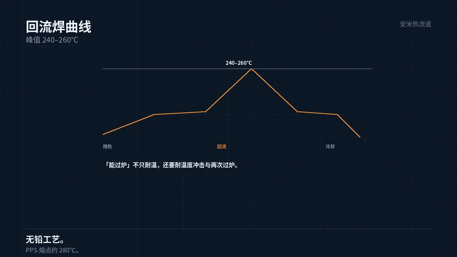
The peak temperature for lead-free reflow soldering is 240–260°C, held for tens of seconds. The profile includes four stages: preheat, soak, reflow, and cooling.
Parts undergo two thermal shocks in the oven: heating and cooling. Fast Cooling causes high internal stress.
Therefore, "reflow withstand" requires not only heat resistance but also resistance to thermal shock and repeated cycles.
PPS melts at approximately 280°C and operates continuously up to 200°C, providing a safety margin above the 260°C peak.
However, margin does not guarantee zero deformation. Dimensional stability after reflow depends on the material's low moisture absorption and high crystallinity.
Why Choose PPS Over PA9T
PA9T has a melting point of 300°C and offers better heat resistance than PPS, but it absorbs moisture at a high rate (0.19%).
High moisture absorption causes water vapor release during reflow, leading to internal blistering and surface wrinkling. This is known as the "popcorn" effect.
Therefore, parts undergoing reflow must be dried first. Pre-reflow drying reduces popcorn risk but adds a process step.
PPS has extremely low moisture absorption, eliminating the need for prolonged drying before reflow and simplifying the process. This is the primary reason for its selection.
Therefore, the key to "PPS withstands reflow" is its low moisture absorption and high crystallinity—not just high heat resistance.
Second reflow carries a higher risk. Internal stress shifts after the first reflow; a second cycle can trigger warpage.
Therefore, base materials for double-sided SMT boards must be validated for "two reflow cycles," not just one.
Between reflows, parts undergo one component placement and one cleaning cycle. Cleaning solvents also impact the material.
Dimensions: Base Hole Positions
The base hole positions serve as the assembly datum for modules, with a typical tolerance of 0.03 mm.
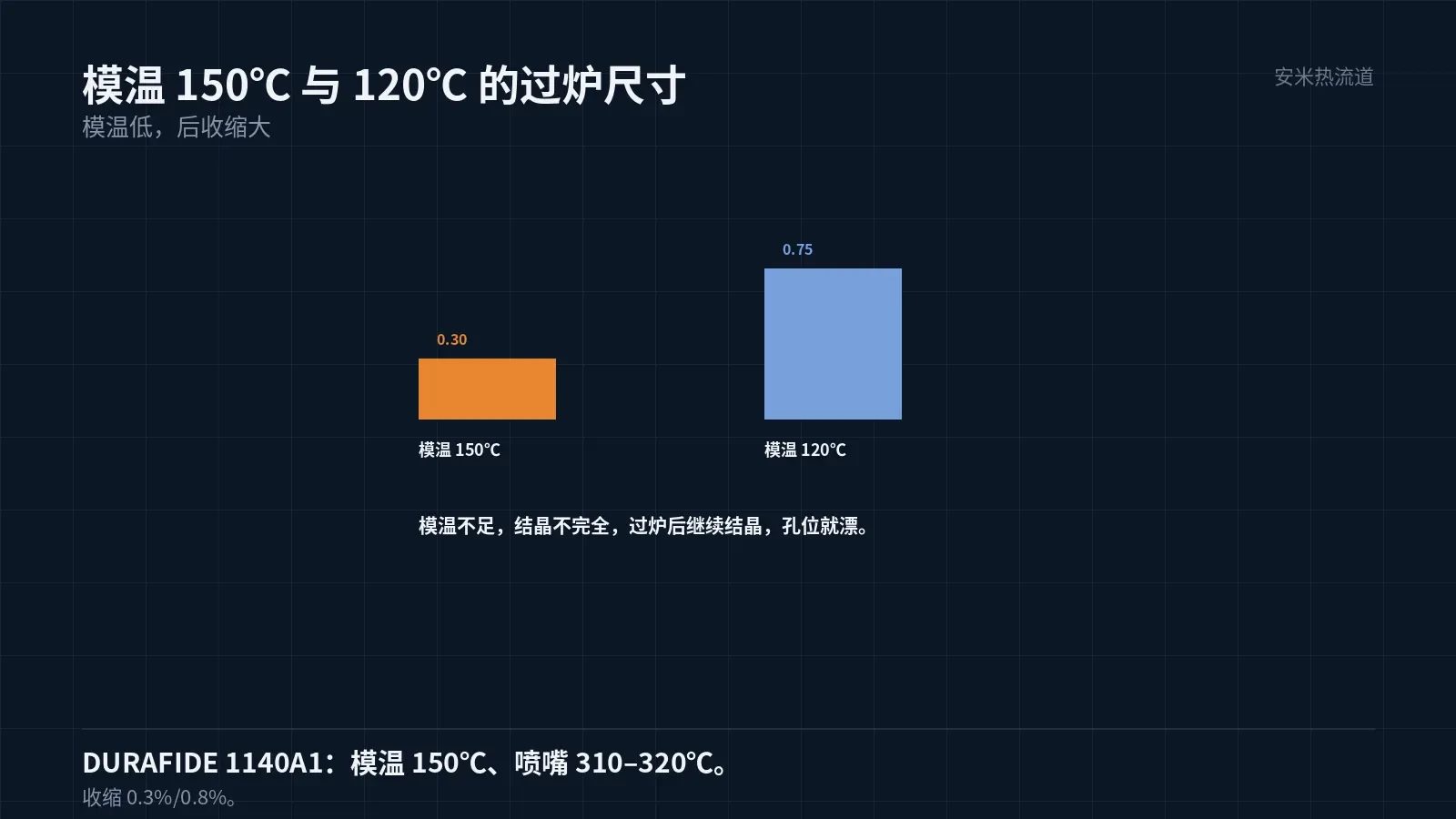
PPS shrinkage with 40% glass fiber: 0.3%/0.8%, directional difference factor 2.7. Align hole orientations with the flow direction.
Dimensional changes after reflow are caused by two factors: thermal expansion and post-shrinkage. PPS has high crystallinity, resulting in low post-shrinkage.
Therefore, PPS offers better dimensional stability after reflow than PA-based materials. This is critical for mass production.
A mold temperature of 150°C is critical. Low mold temperatures cause incomplete crystallization, which leads to further crystallization and dimensional changes during reflow.
Inserts and Terminals
Metal terminals are typically embedded in the base for electrical connection. Terminal positioning accuracy determines assembly quality.
Differential thermal expansion between inserts and plastic creates stress during reflow. PPS has a lower coefficient of linear expansion, generating less stress than PA-based materials.
Two terminal mounting methods are available: in-mold insert molding and post-insertion. In-mold inserts provide high precision but at a higher cost.
Post-insertion is lower cost, but retention force must be verified after insertion. Terminal positions may shift during reflow soldering.
This decision is made during structural review: use in-mold inserts for high-precision requirements, and post-insertion for cost-sensitive applications.
Terminal plating must also be considered. Plating thickness and material affect solder wettability and long-term reliability.
This item is typically specified by the Electrical Assembly team; the material supplier only needs to verify terminal position and retention force.
Retention force testing must be performed after reflow soldering. Adequate pull-out strength at room temperature does not guarantee performance after reflow.
Processing Key Points
Pre-dry PPS at 140°C for 3 hours or 120°C for 5 hours. Although moisture absorption is low, drying is still required, especially for cosmetic parts.
Nozzle temperature: 310–320°C, mold temperature: 150°C, melt temperature must not exceed 360°C. These values apply to DURAFIDE 1140A1..
Vent depth 0.005–0.008mm. PPS has low viscosity; deeper vents cause flash.
Pinpoint gates typically use φ0.8–1.2mm.. For small parts like bases, select the smaller value.
The SD Series is designed for hot runners. PPS viscosity remains stable during extended residence, making it ideal for hot runner applications.
Validation
Base validation includes: dimensions (before and after reflow), appearance (blistering, wrinkling), terminal retention force, and insulation.
Dimensional deviation before and after reflow is the most critical parameter. Excessive deviation prevents mold assembly.
Terminal retention force must be re-measured after reflow. Thermal stress reduces retention force.
Another factor is cleanliness. Flux residue can contaminate the surface, impairing subsequent dispensing or soldering operations.
Cleanliness is verified by measuring ion content in the extraction solution. Acceptance criteria vary by customer standard.
Also inspect for burrs on the surface. On a 0.4mm wall, burrs thicker than the wall will interfere with assembly.
Remove burrs carefully. Excessive grinding alters socket dimensions, affecting insertion and extraction forces.
With a wall thickness of 0.4mm, mold inserts must be tightly fitted. A gap of 0.01mm at the seam leaves a line on the part surface.
This is a mandatory requirement for medical and automotive electronic components, but consumer electronics often allow customer-specific trade-offs.
Please provide the part drawing, hole position tolerances, reflow profile, and terminal structure. We will review material and mold temperature before issuing a quotation.
MATCHED BY MATERIAL AND DEFECT
This article covers stringing, drooling, clogging, and high-heat resins; refer to SD for gate freeze and break-off.
Register for a selection review and quote
Submit part, mold, and material details. Our engineers will evaluate the gate solution per part and provide a quote.
Upload a 2D layout drawing using the form.
Online selection and quote
Scan to register