
Why Does LCP Warp in 0.4mm Pitch Board-to-Board Connectors?
Material Applications17 min read
On this page
Board-to-board connectors are the most precision-critical in connector manufacturing, with pitches of 0.35 or {1.4mm} and dozens to hundreds of pins. A misalignment of just 0.5 mils can cause insertion failure. LCP is the most common material for these components.
LCP offers excellent flowability, high heat resistance, and near-zero moisture absorption, making it theoretically ideal. However, its rapid solidification combined with low mold temperatures often causes warping along the length direction. This article explains the source of this issue.
It Cures Faster Than You Think
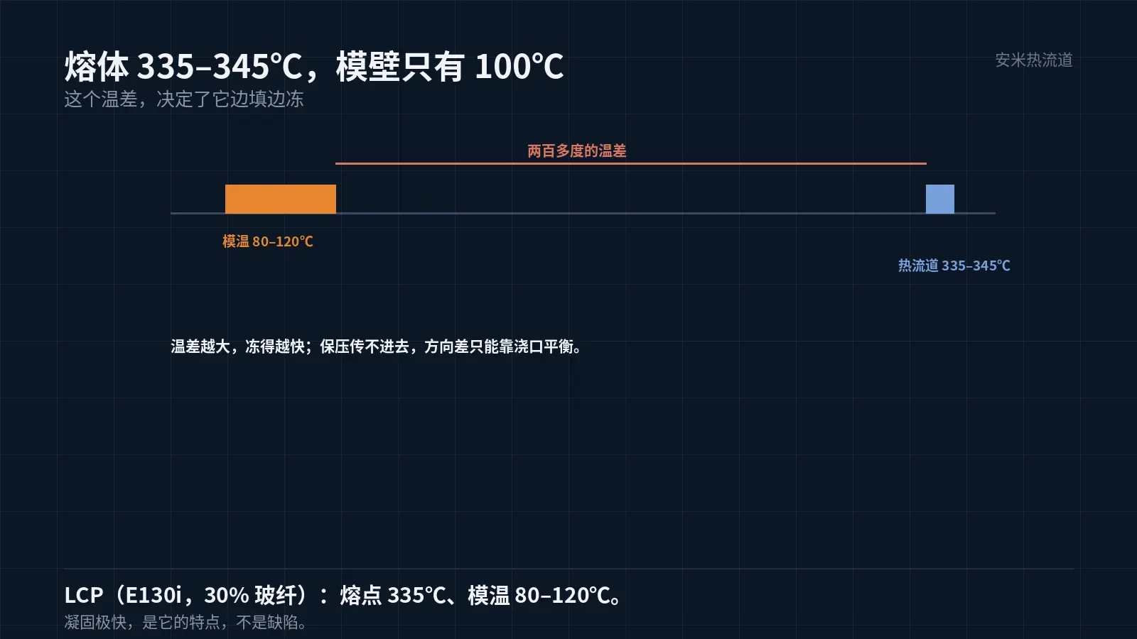
LCP melts at 335°C. Hot runner temperatures range from 335 to 345°C, while mold temperatures are kept low at only 80 to 120°C. This unusually low mold temperature for high-temperature materials isn't meant to reduce cycle time; rapid solidification makes demolding difficult if the mold is hotter.
As soon as the melt enters the cavity and contacts the mold walls at approximately 100°C, solidification begins within tens of milliseconds. This means filling occurs nearly simultaneously with freezing, which prevents pressure transmission to the end and significantly reduces packing and holding effectiveness.
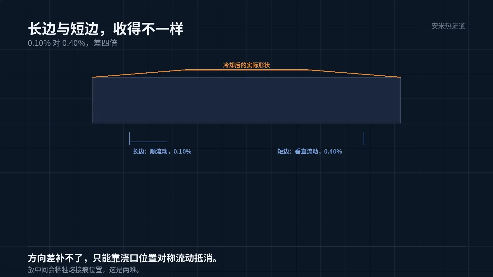
This results in three issues: short shots at the end, weak weld line strength, and the most problematic problem—amplified anisotropic shrinkage. LCP shrinks 0.10% along the flow direction and 0.40% perpendicular to it, a fourfold difference.
For board-to-board connectors measuring 20–30mm in length, this fourfold difference causes warping on the order of tens of microns—right at the edge of coplanarity tolerance limits.
Warping Must Be Calculated by Direction
For board-to-board components, the long edges typically align with the flow direction while the short edges are perpendicular. Long edges experience lower shrinkage than short edges; after cooling, the part contracts toward the short-edge direction, causing the mid-section of the long edges to bow or the ends to sag.
This issue cannot be resolved by extending the holding pressure time. Holding pressure compensates for volumetric shrinkage but not directional variations. To balance directional differences, adjust the gate location and runner design.
A common approach is to inject melt from the center, allowing it to flow symmetrically toward both ends. This cancels shrinkage in two directions at the center but results in weld lines forming in the middle—often where terminals are most densely packed.
Therefore, gate location is always a trade-off: positioning at one end increases warpage, while centering it creates weld lines in critical areas. The decision depends on whether part tolerance is limited by coplanarity or terminal strength.
Our experience indicates: for parts with 0.4mm pitch and up to 60 pins, prioritize coplanarity by offsetting the gate to one end and compensating with zone-controlled mold temperature and holding pressure profiles; for parts with more than 60 pins, prioritize terminal integrity by centering the gate and verifying weld line locations via mold flow analysis.
Benefits of Low Mold Temperature
Mold temperatures of 80–120°C reduce cycle times and energy consumption. LCP molding cycles are typically 30% shorter than PPS cycles, a significant advantage for high-volume board-to-board production.
However, low mold temperature makes uniformity even more critical. With a range of 80°C to 120°C (a 40°C difference), a 10°C variation across cavity zones causes inconsistent crystallization and shrinkage, resulting in region-specific dimensional deviations.
Zone-controlled mold temperature is standard for LCP parts: one zone for the main cavity, one near the gate, and one at the end. Set temperatures based on mold flow analysis, not empirical values.
Additionally, avoid a "higher is better" approach for LCP mold temperature. Higher temperatures cause the melt to freeze faster in the cavity, worsening short shots; lower temperatures lead to poor surface gloss and more visible weld lines. The optimal range lies between these extremes.
Gate: All types except TP Series are supported
According to company records, LCP is compatible with SD, VG, and PVG series but not TP Series, similar to PEEK. Board-to-board applications typically use multi-cavity molds; gate selection must also account for multi-cavity balance.
SD leaves minimal marks and cuts cleanly, ideal for parts with high pin counts and tight spacing. VG and PVG offer higher flow capacity, suitable for molds with many cavities and long flow paths.
In multi-cavity molds, LCP's rapid solidification offers a key advantage: it minimizes fill time variations between cavities, enabling better balance. This is a critical benefit for high-volume board-to-board production.
However, gate diameter must not be too small. LCP has low melt viscosity; undersized gates cause high shear, leading to material degradation and black spots on parts. Determine gate size based on cavity count and part weight, favoring larger diameters.
Drying and Regrinding
LCP has extremely low moisture absorption and less stringent drying requirements, but pre-drying is still necessary before processing. Moisture vaporizes at 335°C, causing silver streaks on parts—especially in thin-walled components.
Control the regrind ratio. LCP's rigid molecular chains degrade easily with repeated heating; post-degradation, flowability increases but strength drops, leading to brittle fracture in thin walls.
Recycled material should generally not exceed 20% and must be thoroughly blended with virgin material. Direct addition of recycled material leads to batch-to-batch degradation in mechanical properties, making it difficult to trace.
Verification: Three Datasets Determine the Solution
Set 1 Coplanarity: Measure before reflow, after one reflow cycle, and after three reflow cycles. Set 2 Terminal Hole Positions: Perform full inspection using pin gauges to analyze hole position distribution. Set 3 Insertion/Extraction Force: Measure post-assembly to check for weakening at weld lines.
Among the three sets, hole position distribution is most indicative. A "dense center, sparse ends" pattern suggests insufficient holding pressure; a "shifted to one end" pattern indicates an incorrect gate location.
Please provide the part drawing, pitch, pin count, number of cavities, and reflow profile. We will adjust gate locations based on directional shrinkage and define mold temperature zones. Pricing will be provided upon solution confirmation.
MATCHED BY MATERIAL AND DEFECT
This article covers stringing, drooling, clogging, and high-heat resins; refer to SD for gate freeze and break-off.
Register for a selection review and quote
Submit part, mold, and material details. Our engineers will evaluate the gate solution per part and provide a quote.
Upload a 2D layout drawing using the form.
Online selection and quote
Scan to register