
Why LCP is Preferred for Millimeter-Wave Radar Covers Even at 0.6mm Thickness?
Material Applications16 min read
On this page
The radar cover is a wave-transparent plastic plate mounted behind the bumper. It must be thin, transparent to waves, and dimensionally stable from −40°C to 85°C.
These three requirements limit material choices. LCP is one option.
Slim Design for Wave Transparency
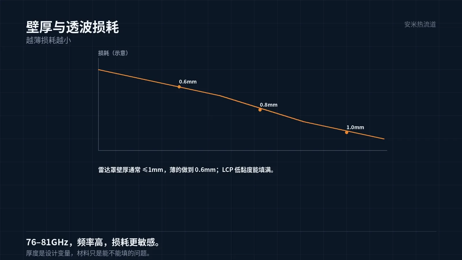
Radar operates at 76–81GHz.. Higher frequencies mean shorter wavelengths, making materials more sensitive to signal loss.
Thinner walls shorten the wave path, reducing loss. Thus, radar cover wall thickness is typically kept under 1mm, with some as thin as 0.6mm..
Thin walls require high flowability. LCP's low melt viscosity enables it to fill 0.6 mm walls—this is the primary reason for its selection.
Thin walls also require rigidity. The cover must withstand stone impact and wind pressure; excessive flexibility causes deformation and misalignment, affecting radar pointing accuracy.
Therefore, thinness and rigidity must coexist: thinness depends on flowability, while rigidity relies on glass fiber. LCP with 30% glass fiber is a common solution for this combination.
Weld lines and assembly must also be considered. The cover is typically secured to brackets via clips or screws, requiring thicker local sections at fixation points than on the cover surface.
Thick fixations and thin surfaces cause uneven wall thickness, resulting in sink marks and warpage. Designers should ensure gradual transitions.
The transition length is set at a 1:3 ratio. An overly abrupt transition causes sink marks on the back of the fixed point, while an overly long one reduces the effective radome wave-transmission area.
Select the correct screws for the fixed point. High torque from metal screws can crack the plastic, so use bushing-based solutions instead.
Bushing must be coaxial with the radome surface. An offset of 0.1 mm causes screw misalignment during assembly and stress concentration in the part.
Stability is achieved via controllable anisotropy.
Radome dimensional stability directly affects radar calibration. A 0.2 mm deformation shifts the beam.
LCP shows high shrinkage anisotropy: For grades with 30% glass fiber, flow-direction shrinkage is 0.10%, while transverse-direction shrinkage is 0.40%, a fourfold difference.
This four-way directional variation means part geometry should align with the flow. For flat parts, extending them longer in the flow direction and shorter across it minimizes the impact of directional shrinkage differences.
If the part is square, differential shrinkage across directions causes warpage. In such cases, either modify the gate or adjust the aspect ratio.
Therefore, LCP stability depends on part geometry. With the same material, long slender parts are stable, while square parts are unstable.
Temperature: −40°C to 85°C Cycling
Temperature cycling is a mandatory requirement for automotive parts. Radar covers must withstand cold in winter, heat in summer, and radiant heat from the engine compartment.
LCP melts at 335°C and has a Tg above 100°C, offering ample margin for long-term exposure to 85°C.
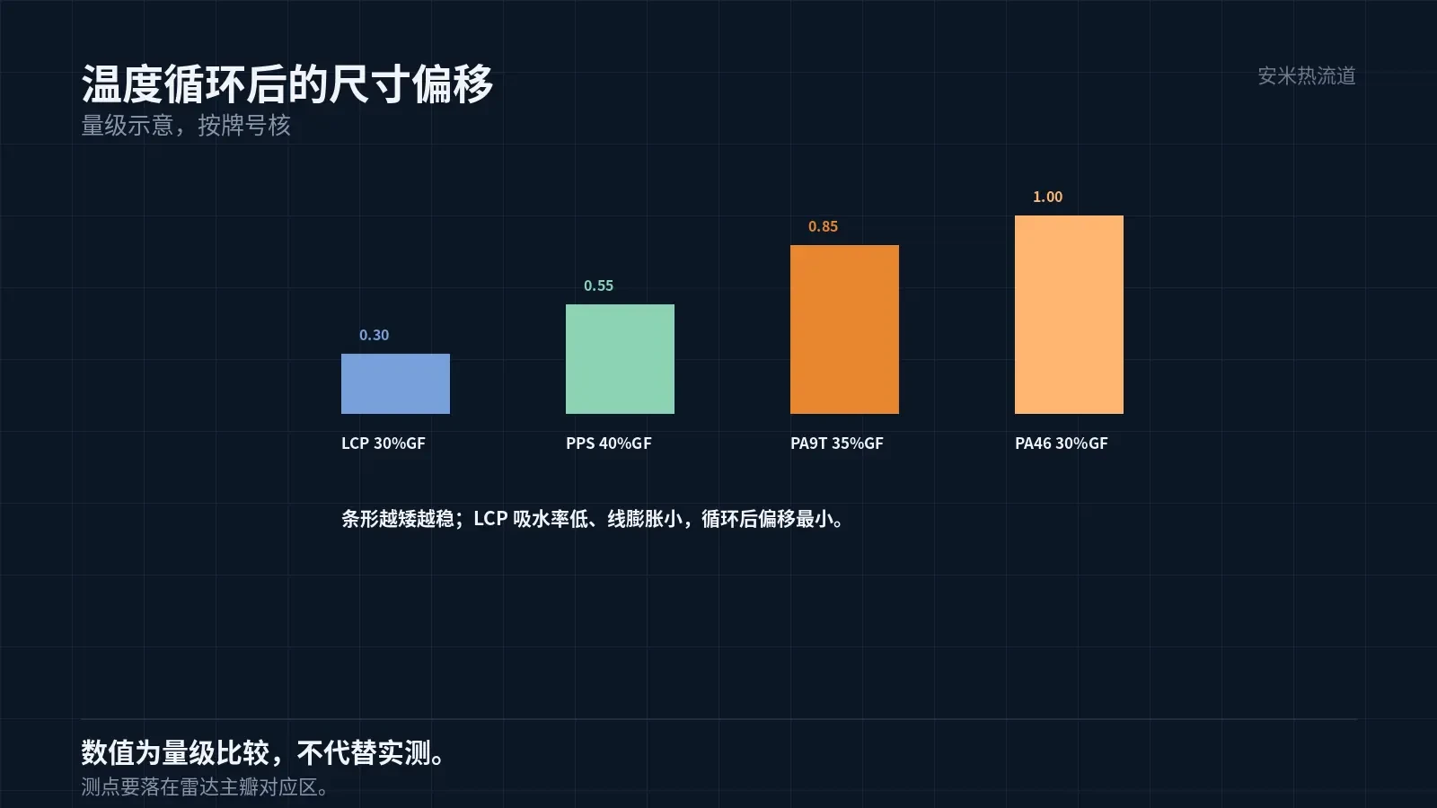
Temperature cycling induces minor dimensional changes. Due to its low coefficient of linear expansion and strong anisotropy, LCP exhibits smaller dimensional shifts after cycling compared to PA-based materials.
This is the second reason for using LCP in radar covers: dimensional stability during temperature cycling.
Moisture absorption is a concern. LCP exhibits low water uptake, so humidity has minimal effect on dimensions—advantageous compared to PA9T and PA46.
Mold Temperature and Gate
LCP mold temperature is typically 80–120°C. Low mold temperatures cause rapid solidification and strong orientation, leading to significant directional variation. High mold temperatures reduce orientation but increase cycle time.
For thin-walled components like radar domes, use medium-to-high mold temperatures to prevent premature melt solidification during filling.
Gate types SD, VG, and PVG are suitable for LCP; TP is not recommended. SD is commonly used for thin-walled parts due to its simple structure and low pressure loss.
Gate locations must avoid the radar's irradiation zone. Orientation and shrinkage at gates differ from other areas, creating an "anomalous region."
This must be flagged during structural review: gate, runner, and ejector pin positions cannot fall within the radar's main lobe area.
Surface and Coatings
The outer surface of radar domes is typically painted to match the bumper color. Due to LCP's low surface energy and poor adhesion, pre-treatment is required before coating.
Treatment uses plasma or flame to increase surface energy. Painting must be done within a specified time after treatment; exceeding this limit renders the treatment ineffective.
Paint thickness must also be controlled. Excessive paint thickness increases millimeter-wave attenuation, degrading radar performance.
Therefore, radar dome coating is not standard cosmetic paint. The paint's dielectric properties and thickness must be verified to meet radar performance requirements.
The appearance team often overlooks this issue. While the paint finish looks good, radar performance fails and the root cause remains undetected.
Acceptance and Testing
Radome acceptance covers three categories: dimensions (including after thermal cycling), wave transmission (dielectric constant and loss tangent), and appearance (coating and defects).
Select dimensional measurement points within the main lobe region only. Arbitrary selection invalidates the data.
Wave transmission testing requires dedicated fixtures and must adhere to the customer's specified frequency band. Results from different frequency bands cannot be extrapolated.
Appearance acceptance must include "invisible defects" such as internal voids, weld lines, and glass fiber agglomeration. These defects impact wave transmission.
The part can only be installed if all three groups pass. Missing any group will reveal issues at the vehicle level.
Provide wall thickness, radar frequency band, thermal cycling requirements, and coating process. We will verify material and gate design before quoting.
MATCHED BY MATERIAL AND DEFECT
This article covers stringing, drooling, clogging, and high-heat resins; refer to SD for gate freeze and break-off.
Register for a selection review and quote
Submit part, mold, and material details. Our engineers will evaluate the gate solution per part and provide a quote.
Upload a 2D layout drawing using the form.
Online selection and quote
Scan to register