
Can PPS Withstand 800V in E-Drive Power Components?
Material Applications16 min read
On this page
As platform voltage rises from 400V to 800V, insulation material selection changes. Many applications previously using PA66 have switched to PPS.
The change is driven by tracking resistance and long-term heat resistance, not mechanical strength.
What 800V Changes
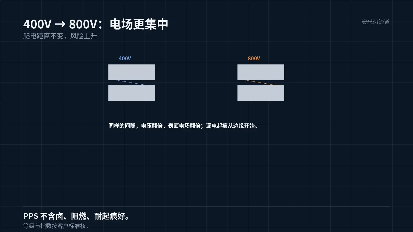
Doubling the voltage doubles the electric field strength. For the same creepage distance, surface electric fields become more concentrated, increasing the risk of electrical tracking.
Electrical tracking is surface carbonization caused by arcing, which creates conductive paths. Once it forms, insulation fails permanently.
Therefore, for high-voltage components, the primary material requirement is tracking resistance, not mechanical strength.
PPS offers halogen-free composition, flame retardancy, and excellent tracking resistance. These properties make it a common choice for high-voltage insulation components.
Note that specific grades and indices must be verified against customer standards, as criteria vary by customer.
Another advantage of PPS is dimensional stability. Its extremely low moisture absorption minimizes humidity-induced dimensional changes, which is critical for precision high-voltage components.
PA materials swell upon moisture absorption, altering connector fits. PPS avoids this issue, ensuring stable insertion and extraction forces.
However, PPS has low toughness. Connectors are prone to edge chipping under impact; designs must include fillets and cushioning.
PPS offers stable dimensions and good insulation but lower toughness than PA. Material selection depends on the part type.
Toughness can be enhanced by adding elastomers or selecting grades with lower glass fiber content. However, stiffness and heat resistance will also change and must be validated together.
Common connector practice: use low-glass-fiber material for clips and high-glass-fiber material for housings in two-shot molding.
Heat Resistance: Withstands Long-Term High Temperatures, Not Just Melting Point
PPS melts at approximately 280°C and has a long-term service temperature of around 200°C (depending on grade and specification).
Electric drive component temperatures are not constant. Stall, overload, or cooling failure can cause short-term local temperature spikes.
PPS offers excellent short-term heat resistance and a wide processing window, with melt temperatures up to 360°C. This makes it ideal for power components.
Polyplastics DURAFIDE 1140A1 is a 40% glass-filled grade. Recommended nozzle temperatures: 310–320°C; mold temperature: 150°C.
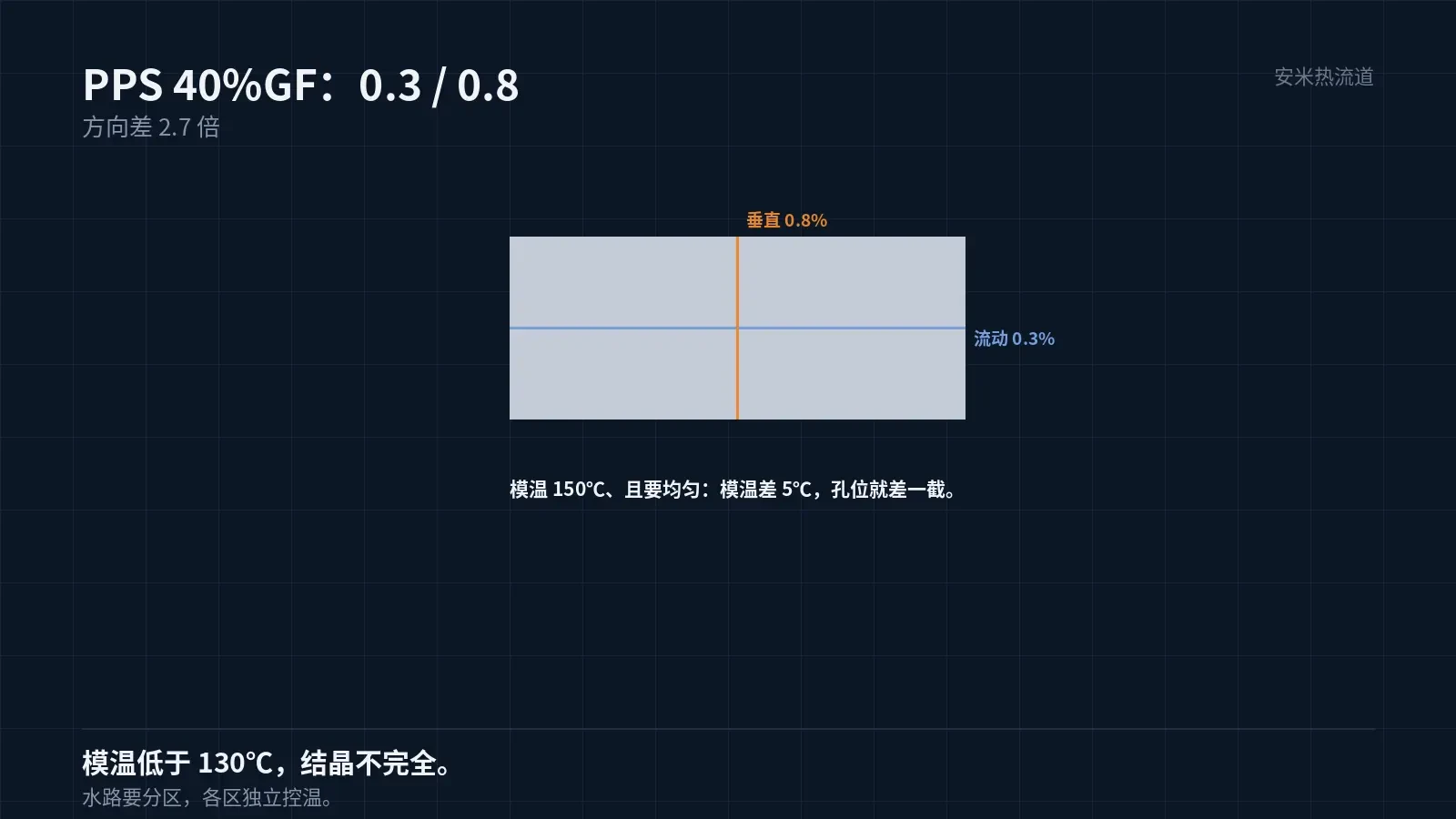
Mold temperature must be above 130°C. Low mold temperatures cause incomplete PPS crystallization, resulting in poor part toughness and surface quality.
Dimensions: PPS Shrinkage and Warpage
Shrinkage for 40% glass-filled PPS: 0.3% in flow direction, 0.8% in transverse direction. The directional difference is approximately 2.7 times—smaller than LCP but still significant.
Electrical components have tight dimensional tolerances, especially for insert locating holes. A hole position deviation of 0.1mm can cause assembly issues.
Methods to control dimensions: gate location, uniform mold temperature, and adequate holding pressure. Of these three, uniform mold temperature is the most critical.
Non-uniform mold temperature causes uneven part shrinkage and hole position deviation. Therefore, PPS molds require zoned cooling channels.
Additionally, PPS has high crystallinity, so most shrinkage occurs inside the mold. This is an advantage over PA materials, resulting in less dimensional change after ejection.
Inserts and Overmolding
Most electric drive components include metal inserts for electrical conduction or fixation. Differences in thermal expansion coefficients between the insert and plastic create internal stress.
PPS has a low linear coefficient of thermal expansion, closer to that of metals than PA materials. This is an advantage for insert-molded parts.
Ensure overmold thickness is sufficient. A plastic layer that is too thin around the insert may crack due to restraint during cooling.
Empirically, the plastic layer thickness around the insert should be at least 1.5mm.. Specific values depend on part dimensions and insert material.
Inserts require preheating. Contact between cold inserts and hot melt causes instantaneous interface cooling, leading to poor adhesion and high stress.
Three Processing Considerations
First, dry the material. PPS must be pre-dried at 140°C for 3 hours or at 120°C for 5 hours. Skipping this step causes moisture in the melt to result in surface whitening and reduced strength.
Second, residence time. PPS viscosity does not rise significantly during extended hold times; this is a key characteristic. Therefore, hot runners are suitable.
Note that stable viscosity does not mean the material is undegraded. Excessive temperature or time can still cause degradation. Melt temperature must not exceed 360°C.
Third, venting. PPS melt has low viscosity and easily flows into vent grooves. Vent groove depth must be controlled at 0.005–0.008mm..
Of these three points, venting is the most prone to issues. If the groove is too deep, flash occurs; if too shallow, burn marks appear. The depth must be determined by material properties, not based on experience.
Validation
Electric drive component validation: withstand voltage, insulation resistance, proof tracking index, temperature cycling, and vibration. All five tests are required.
Proof tracking tests must comply with customer standards. Since voltage levels, cycle counts, and acceptance criteria differ by standard, results are not mutually recognized.
Insulation resistance after thermal cycling is the most likely failure mode. The number of cycles is determined by the vehicle's lifetime requirements.
Another often overlooked item is cleanliness. Surface contaminants degrade insulation and can cause tracking.
Please provide the voltage platform, insulation class, temperature requirements, and insert structure. We will verify against material and gate design and provide a quote upon confirmation.
MATCHED BY MATERIAL AND DEFECT
This article covers stringing, drooling, clogging, and high-heat resins; refer to SD for gate freeze and break-off.
Register for a selection review and quote
Submit part, mold, and material details. Our engineers will evaluate the gate solution per part and provide a quote.
Upload a 2D layout drawing using the form.
Online selection and quote
Scan to register